RICOH Step Down DC DC Converter with LDO and Reset RP901 Series User Guide
Summary
This advanced power management IC is a highly integrated PWM step-down DC/DC converter, combining robust voltage regulation with an LDO and Voltage Detector (VD). Ideal for embedded system designers needing reliable, compact, and high-efficiency power solutions on dense PCBs. The comprehensive manual details its performance characteristics, including low ripple output, multiple protection circuits (UVLO, Overcurrent), soft-start functionality, and precise operation across varying load conditions. Use this guide to efficiently design systems requiring stable voltage outputs ranging from 1.2V–3.3V with minimal external components.
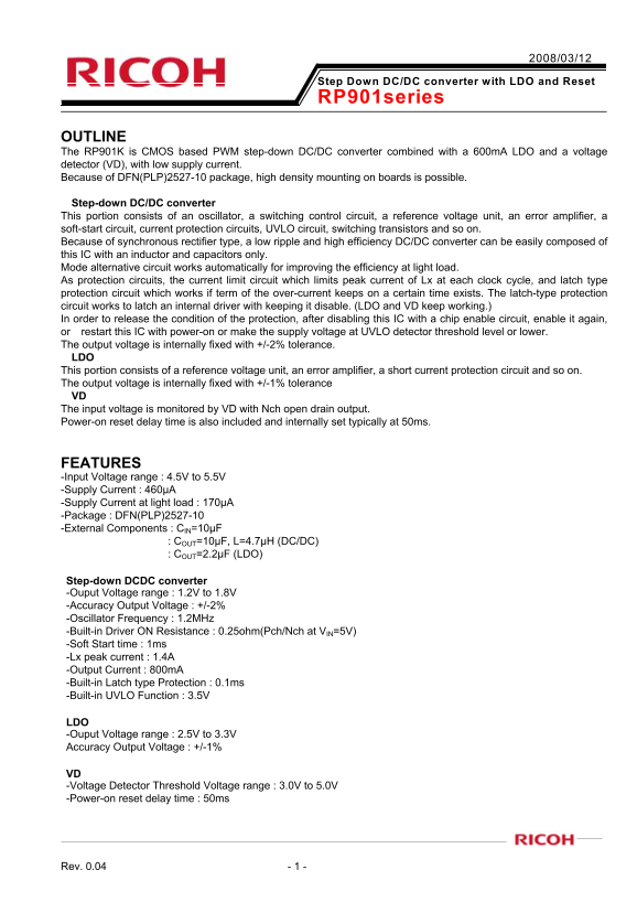
Page 1 Text Content
Step Down DC/DC converter with LDO and Reset RP901series
OUTLINE The RP901K is CMOS based PWM step-down DC/DC converter combined with a 600m A LDO and a voltage detector (VD), with low supply current. Because of DFN(PLP)2527-10 package, high density mounting on boards is possible.
Step-down DC/DC converter This portion consists of an oscillator, a switching control circuit, a reference voltage unit, an error amplifier, a soft-start circuit, current protection circuits, UVLO circuit, switching transistors and so on. Because of synchronous rectifier type, a low ripple and high efficiency DC/DC converter can be easily composed of this IC with an inductor and capacitors only. Mode alternative circuit works automatically for improving the efficiency at light load. As protection circuits, the current limit circuit which limits peak current of Lx at each clock cycle, and latch type protection circuit which works if term of the over-current keeps on a certain time exists. The latch-type protection circuit works to latch an internal driver with keeping it disable. (LDO and VD keep working.) In order to release the condition of the protection, after disabling this IC with a chip enable circuit, enable it again, or restart this IC with power-on or make the supply voltage at UVLO detector threshold level or lower. The output voltage is internally fixed with +/-2% tolerance. LDO This portion consists of a reference voltage unit, an error amplifier, a short current protection circuit and so on. The output voltage is internally fixed with +/-1% tolerance VD The input voltage is monitored by VD with Nch open drain output. Power-on reset delay time is also included and internally set typically at 50ms.
FEATURES -Input Voltage range : 4.5V to 5.5V -Supply Current : 460µA -Supply Current at light load : 170µA -Package : DFN(PLP)2527-10 -External Components : CIN=10µF : COUT=10µF, L=4.7µH (DC/DC) : COUT=2.2µF (LDO)
Step-down DCDC converter -Ouput Voltage range : 1.2V to 1.8V -Accuracy Output Voltage : +/-2% -Oscillator Frequency : 1.2MHz -Built-in Driver ON Resistance : 0.25ohm(Pch/Nch at VIN=5V) -Soft Start time : 1ms -Lx peak current : 1.4A -Output Current : 800m A -Built-in Latch type Protection : 0.1ms -Built-in UVLO Function : 3.5V
LDO -Ouput Voltage range : 2.5V to 3.3V Accuracy Output Voltage : +/-1%
VD -Voltage Detector Threshold Voltage range : 3.0V to 5.0V -Power-on reset delay time : 50ms
Rev. 0.04 - 1 -
Page Summary Contents For RICOH Step Down DC DC Converter with LDO and Reset RP901 Series User Guide
Manual Details
| Brand | Ricoh |
|---|---|
| Pages | 6 |
| File Size | 136.57 KB |
| Published | May 27, 2026 |
Enter the captcha to get the download link:

Frequently Asked Questions
What is the required total external capacitance for the DC/DC converter?
The DC/DC portion requires a 10µF capacitor (IN) and a 4.7µH inductor (IN).
How does the IC handle over-current conditions?
It has built-in latch type protection that prevents an internal driver from operating when over-current occurs. Restarting or enabling again is needed to reset it.
What are the output voltage ranges and accuracies for the LDO component?
The LDO's output range is 2.5V to 3.3V, with an accuracy of +/-1% tolerance.
What is the power-on detection sequence delay time?
The Voltage Detector (VD) has a Power-on reset delay time that is internally set at typically 50ms.