RICOH RP901K Series PWM VFM Step-down DC DC Converter with Synchronous Rectifier, VR and VD Data Manual and User Guide
Summary
This professional DC/DC converter package provides integrated power management solutions for complex systems. Featuring PWM/VFM step-down conversion, an LDO regulator, and dual voltage detection (VR/VD), it supplies multiple stable power rails from a single source while optimizing efficiency. The manual details operational modes—including automated VFM switching—along with comprehensive specifications, protection features like fold-back circuitry, and application guidance for various embedded electronics, such as handheld or battery-powered equipment.
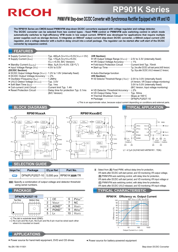
Page 1 Text Content
RP901K Series
PWM/VFM Step-down DC/DC Converter with Synchronous Rectifier Equipped with VR and VD
The RP901K Series are CMOS-based PWM/VFM step-down DC/DC converters equipped with voltage regulator and voltage detector. The DC/DC converter can be selected from two control types - fixed PWM control or PWM/VFM auto switching control in which mode automatically switches to high-efficiency VFM mode in low output current. RP901K was developed for applications that require multiple power supplies such as storage devices. It integrates an 800m A∗ output current step-down DC/DC converter, a 600m A output current LDO regulator, and a voltage detector with a built-in delay circuit into a small package. The regulator can be started after soft start of the DC/DC converter by sequence control.
FEATURES • Supply Current (IDD1)·······················Typ. 460μA (VIN=VCE=5.5V,VOUT1= 0V) (VR Section) • Supply Current (IDD2)·······················Typ. 170μA (VIN=VCE=5.5V, • VR Output Voltage Range (VOUT2)····· 2.5V to 3.3V (internally fixed) VOUT1=5.5V, B/C Version) • VR Output Voltage Accuracy·········· ± 1% • Standby Current (Istandby)··················Max. 5μA (VIN=5.5V, CE="L") • Fold-back Protection Circuit ········· Current limit Typ. 70m A • Input Voltage Range (VIN) ···············4.5V to 5.5V • Start-up Time·································· Typ. 2ms after DC/DC soft start period (A/B Version)
(DC/DC Section) Typ. 50μs after DC/DC UVLO released (C Version)
• DC/DC Output Voltage Range (VOUT1) ··1.2V to 1.8V (internally fixed) • Auto-Discharge function • DC/DC Output Voltage Accuracy····± 2% (VD Section) • Oscillator Frequency (fosc)···············1.2MHz • VD Detector Threshold Range (-VDET)··· 2.0V to 3.0V (internally fixed) • UVLO Detect Voltage (VUVLO) ·········Typ. 3.5V (A Version, VR Output voltage monitoring) • Soft Start Time (tstart)···························Typ. 1ms 3.0V to 5.0V (internally fixed) • Coil-current Limit Circuit ·················Current limit Typ. 1.4A (B/C Version, Input voltage monitoring) • Reset Protection Circuit··················Delay time for protection Typ. 0.1ms • VD Detector Threshold Accuracy··· ± 2%
(B/C Version) • VD Output Delay Time ··················· Typ. 50ms • Thermal Shutdown Circuit·············· Stops at 165°C • Package ········································· DFN(PLP)2527-10
∗) This is an approximate value, because output current depending on conditions and external parts.
BLOCK DIAGRAMS TYPICAL APPLICATION
RP901Kxxx A ff ic ie RP901Kxxx B/C
PVDD PVDD
Chip Ramp Current Chip Ramp Current
CE Compensation Feedback CE Enable Compensation Feedback R1 50KΩ
Enable
OSC Current AVDD VDOUT VDOUT
OSC Current LX
Protection LX Protection
PVDD VOUT1
Vref “H”active L1
Vref PWM Switching Switching
PWM/VFM Control CE LX VOUT1
Control Control Control 4.7μH
Soft VOUT1 Soft VOUT1 PGND VOUT2 VOUT2
Start UVLO Start UVLO
C1 AGND C2 C3
PGND PGND
AVDD Thermal Ceramic Ceramic Ceramic
Thermal Vref Shutdown AGND
Vref Shutdown AGND
Delay Circuit
VDOUT Vref Current VDOUT
Vref Current VOUT2 Protection L1 4.7μH (VLF4014AT-4R7M1R1 : TDK)
VOUT2 Protection
Delay Circuit
SELECTION GUIDE
.∗ : Select from (.A.) Fixed PWM, without delay time for protection,
Halogen Free Package Q'ty per Reel Part No.
VR starts after DC/DC soft start period, and VD monitoring VR output voltage,
DFN(PLP)2527-10 5,000 pcs RP901K .xxx∗ -TR (.B.) PWM/VFM auto switching control, with delay time for protection,
VR starts after DC/DC soft start period, and VD monitoring VR input voltage or
.xxx :Specify a combination of output voltage and detector threshold
(.C.) PWM/VFM auto switching control, with delay time for protection,
using serial numbers.
VR starts after DC/DC UVLO released, and VD monitoring VR input voltage.
PACKAGE TYPICAL CHARACTERISTIC
DFN(PLP)2527-10 RP901K Efficiency vs. Output Current
1 CE 6 PVDD SET VOUT1=1.8V, VIN=5.0V
Bottom View Top View
2 VDOUT 7 NC 3 AGND∗∗ 8 VOUT1
4 PGND∗∗ 9 AVDD 5 LX 10 VOUT2
∗) The tab is substrate level (GND). ∗∗) No.3 pin and No.4 pin, No.6 pin and No.9 pin must be wired each other
A version
when it is mounted on board. B version
Output Current IOUT1 (m A)
APPLICATIONS • Power source for hand-held equipment, DVD and CD drives • Power source for battery-powered equipment No.EK-156-111001 Step-down DC/DC Converter
Page Summary Contents For RICOH RP901K Series PWM VFM Step-down DC DC Converter with Synchronous Rectifier, VR and VD Data Manual and User Guide
Manual Details
| Brand | Ricoh |
|---|---|
| Pages | 2 |
| File Size | 170.54 KB |
| Published | June 04, 2026 |
Enter the captcha to get the download link:

Frequently Asked Questions
What is the operating voltage range (VIN)?
The input voltage range is 4.5V to 5.5V.
Can I run the device in automatic switching mode?
Yes, it supports PWM/VFM auto-switching control, which efficiently switches to VFM mode at low output currents.
What safety features are included?
It includes Fold-back Protection Circuit (Current limit Typ. 70mA), Reset Protection, and Thermal Shutdown Circuit (Stops at 165°C).
How is the DC/DC section started up?
With Version A, it has a soft start time of Typ. 2ms; with Version C, the start-up is typ. 50μs after DC/DC UVLO released.