# A B C D E F G H I J K L M N O P Q R S T U V W X Y Z

RICOH R1218x SERIES Step-up DC DC Converter for White LED Backlight User Guide and Specifications

Summary

The R1218x series is a high-efficiency, PWM control step-up DC/DC converter IC specifically designed for constant current white LED backlighting. This manual provides comprehensive details on the device's operation, including its built-in protection circuits (OVP, UVLO), low voltage inputs, and dimming control options. It is ideal for engineers developing portable equipment or lighting systems that require reliable, efficient, and regulated high-output white LED illumination.
📄 Preview PAGE OF 19

Page 1 Text Content

R1218x SERIES

Step-up DC/DC converter for White LED Backlight

NO.EA-166-111123

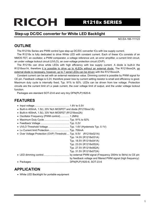
OUTLINE The R1218x Series are PWM control type step-up DC/DC converter ICs with low supply current. The R1218x is fully dedicated to drive White LED with constant current. Each of these ICs consists of an NMOS FET, an oscillator, a PWM comparator, a voltage reference unit, an error amplifier, a current limit circuit, an under voltage lockout circuit (UVLO), an over-voltage protection circuit (OVP). The R1218x can drive white LEDs with high efficiency with low supply current. A diode is built-in the R1218xxx1A, therefore it is possible to drive up to 4LEDs without an external diode. The R1218xxx2A, an external diode is necessary, however, up to 7 serial LEDs can be driven with the R1218xxx2A. Constant current can be set with an external resistance value. Dimming control is possible by PWM signal for CE pin. Feedback voltage is 0.2V, therefore power loss by current setting resistor is small and efficiency is good. Maximum duty cycle is internally fixed, Typ. 91% to 92%. LEDs can be driven from low voltage. Protection circuits are the current limit of Lx peak current, the over voltage limit of output, and the under voltage lockout function. Packages are standard SOT-23-6 and very tiny DFN(PLP)1820-6.

FEATURES • Input voltage.................................................. 1.8V to 5.5V • Built-in 400m A, 1.5Ω, 20V Nch MOSFET and diode (R1218xxx1A) • Built-in 400m A, 1.5Ω, 33V Nch MOSFET (R1218xxx2A) • Oscillator Frequency (PWM control)............. 1.2MHz • Maximum Duty Cycle Typ. 91% to 92% • Feedback Voltage Typ. 0.2V • UVLO Threshold Voltage Typ. 1.6V (Hysteresis Typ. 0.1V) • Lx Current limit Protection............................. Typ. 700m A • Over Voltage Protection (OVP) Threshold.... Typ. 9.5V (R1218x021A)

Typ. 14.0V (R1218x031A) Typ. 18.5V (R1218x041A) Typ. 23.0V (R1218x052A) Typ. 27.5V (R1218x062A) Typ. 31.5V (R1218x072A)

• LED dimming control..................................... by external PWM signal (Frequency 200Hz to 5k Hz) to CE pin

by feedback voltage and filtered PWM signal (high frequency)

• Packages DFN(PLP)1820-6, SOT-23-6

APPLICATION • White LED Backlight for portable equipment

Page Summary Contents For RICOH R1218x SERIES Step-up DC DC Converter for White LED Backlight User Guide and Specifications

Page 1 R1218x SERIES Step-up DC/DC converter for White LED Backlight NO.EA-166-111123 OUTLINE The R1218x Series are PWM control type step-up DC/DC converter ICs with low supply current. The R1218x is fully d...
Page 2 BLOCK DIAGRAMS R1218xxx1A VFB VIN LX VOUT Error Amp UVLO PWM Comp Switch Control Slope Current Current Compensation Protect sense Shutdown Chip Enable delay CE GND R1218xxx2A VFB VIN LX VOUT Error Amp...
Page 3 SELECTION GUIDE The OVP threshold, the built-in diode, and the package for the ICs can be selected at the user’s request. Product Name Package Quantity per Reel Pb Free Halogen Free R1218Kxxxx-TR DFN(...
Page 4 PIN CONFIGURATIONS • DFN(PLP)1820-6 • SOT-23-6 Top View Bottom View (mark side) PIN DESCRIPTIONS • DFN(PLP)1820-6 Pin No Symbol Pin Description 1 CE Chip Enable Pin ("H" Active) 2 VFB Feedba...
Page 5 ABSOLUTE MAXIMUM RATINGS (GND=0V) Symbol Item Rating Unit VIN VIN Pin Voltage 6.5 V VCE CE Pin Voltage −0.3 to VIN+0.3 V VFB VFB Pin Voltage −0.3 to VIN+0.3 V R1218xxx1A −0.3 to 22 VOUT VOUT Pin Volta...
Page 6 ELECTRICAL CHARACTERISTICS • R1218xxxx A Topt=25°C Symbol Item Conditions Min. Typ. Max. Unit VIN Input Voltage 1.8 5.5 V IDD Supply Current VIN=5.5V, VFB=0V, Lx at no load 0.5 1.0 m A Istandby Standb...
Page 7 TYPICAL APPLICATIONS VIN LX VIN LX CE VOUT CE VOUT GND VFB R1 GND VFB • LED Current setting LED current can be set with feedback resistor(R1) ILED=0.2 / R1 • LED Dimming Control, Softstart (1) LED dim...
Page 8 (2) Dimming control by DC voltage LED dimming control is also possible by using the DC voltage to VFB pin. LED current is adjustable by DC voltage and resistors, R1 and R2 in the following figure. ILE...
Page 9 • Selection of Inductors The peak current of the inductor at normal mode can be calculated as next formula: ILXpeak=1.25 × ILED × VOUT / VIN + 0.5 × VIN × (VOUT − VIN) / (L × VOUT × fosc) When the sta...
Page 10 ff ic ie ff ic ie ff ic ie TYPICAL CHARACTERISTICS 1) Efficiency vs. LED Current (2LED) L:LQH32CN220 (Topt=25°C) R1218x021A R1218x021A VIN=1.8V VIN=3.6V ff ic ie ff ic ie LED Current l LED (m A) LED C...
Page 11 ff ic ie ff ic ie ff ic ie VIN=4.2V LED Current l LED (m A) 3) Efficiency vs. LED Current (4LED ) L: LQH32CN220 (Topt=25°C) R1218x041A R1218x041A ff ic ie VIN=2.7V VIN=3.6V LED Current l LED (m A) LED...
Page 12 ff ic ie ff ic ie ff ic ie 4) Efficiency vs. LED Current (6LED) L: LQH32CN220, Diode: CRS02 (Topt=25°C) VIN=2.7V VIN=3.6V LED Current l LED (m A) ff ic ie LED Current l LED (m A) ff ic ie VIN=4.2V LED...
Page 13 ff ic ie tp lt rr l L VIN=4.2V lt (V LED Current ILED (m A) 6) PWM Dimming Control (2LED) VIN=3.6V, R1=10Ω 6-1. Duty vs. LED Current (2LED) (Topt=25°C) tp lt R1218x021A 25.0 5k Hz 1k Hz 200Hz Duty (%)...
Page 14 rr l L tp lt rr l L 7) PWM Dimming Control (4LED) VIN=3.6V, R1=10Ω 7-1. Duty vs. LED Current (4LED) (Topt=25°C) R1218x041A 25.0 22.5 20.0 5k Hz 1k Hz lt 200Hz Duty (%) tp lt 7-2. Output Voltage Wavefo...
Page 15 rr IL tp lt tp lt 8-2. Output Voltage Waveform (6LED) (Topt=25°C) R1218x062A R1218x062A fosc=200Hz fosc=5k Hz CE Input Voltage CE Input Voltage Output Voltage Output Voltage Time (ms) Time (ms) tp lt ...
Page 16 te to re ld ill to re lt 10) VFB Voltage vs. Temperature 11) UVLO Detector Threshold/Released Voltage vs. Temperature R1218x041A R1218x041A VIN=3.6V VIN=3.6V UVLO Released 0.195 1.58 UVLO Detector Tem...
Page 17 te to re ld te to re ld Lx ur re nt im it Il im (m A) 16) LX Current Limit vs. Temperature VIN=1.8V VIN=2.4V VIN=3.6V VIN=5.5V Temparature Topt (℃) 17) OVP Transient Response (Topt=25°C) te to re ld O...
Page 18 ff ic ie 18) Efficiency dependence on inductors (4 LED) R1218x041A (Intemal Diode Type) VIN=3.6V LQH32CN220K53 LQH32CN100K53 GLF2012T220K GLF2012T100K LED Current l LED (m A)
Page 19 1. The products and the product specifications described in this document are subject to change or discontinuation of production without notice for reasons such as improvement. Therefore, before decid...

Manual Details

Brand Ricoh
Pages 19
File Size 306.76 KB
Published June 02, 2026
71 views

Enter the captcha to get the download link:

captcha

Frequently Asked Questions

What is the required input voltage for the R1218x converter?

The recommended input voltage (VIN) ranges from 1.8V to 5.5V.

How can I control the brightness of the LED backlight?

Dimming is achieved using an external PWM signal applied directly to the CE pin.

Which version supports driving more than four LEDs, and how many?

The R1218xxx2A requires an external diode but can drive up to 7 serial LEDs.

Is power loss minimal when setting constant current?

Yes, because the feedback voltage is only 0.2V, resulting in small power loss.