Philips Semiconductors BYV29B-500 Data Sheet
Summary
This ultra-fast epitaxial rectifier diode is engineered for demanding high-frequency switched mode power supplies, acting as a reliable output rectifier. Featuring low forward voltage drop, fast switching times, and soft recovery characteristics, this component delivers high efficiency and superior thermal performance under adverse conditions. The technical specification sheet provides electrical parameters, lifetime rating tables, comprehensive thermal impedance data ($Z_{th}$), and mechanical dimensions crucial for power electronics designers and engineers integrating advanced rectifiers into their designs.
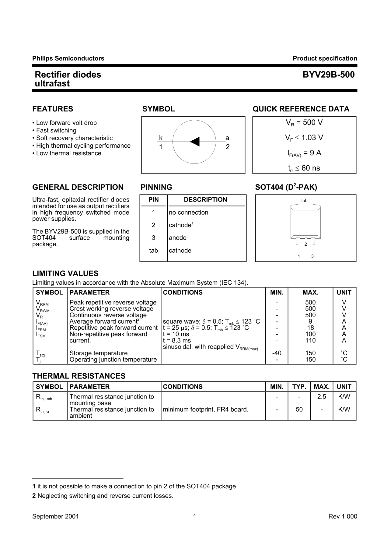
Page 1 Text Content
Philips Semiconductors Product specification
Rectifier diodes BYV29B-500 ultrafast
FEATURES SYMBOL QUICK REFERENCE DATA • Low forward volt drop VR = 500 V • Fast switching • Soft recovery characteristic VF ≤ 1.03 V • High thermal cycling performance • Low thermal resistance IF(AV) = 9 A
trr ≤ 60 ns
GENERAL DESCRIPTION PINNING SOT404 (D2-PAK) Ultra-fast, epitaxial rectifier diodes PIN DESCRIPTION tab intended for use as output rectifiers in high frequency switched mode no connection power supplies.
cathode1
The BYV29B-500 is supplied in the SOT404 surface mounting anode package.
tab cathode
LIMITING VALUES Limiting values in accordance with the Absolute Maximum System (IEC 134). SYMBOL PARAMETER CONDITIONS MIN. MAX. UNIT VRRM Peak repetitive reverse voltage VRWM Crest working reverse voltage VR Continuous reverse voltage IF(AV) Average forward current2 square wave; δ = 0.5; Tmb ≤ 123 ˚C IFRM Repetitive peak forward current t = 25 µs; δ = 0.5; Tmb ≤ 123 ˚C IFSM Non-repetitive peak forward t = 10 ms
current. t = 8.3 ms
sinusoidal; with reapplied VRRM(max)
Tstg Storage temperature -40 ˚C Tj Operating junction temperature ˚C
THERMAL RESISTANCES SYMBOL PARAMETER CONDITIONS MIN. TYP. MAX. UNIT Rth j-mb Thermal resistance junction to 2.5 K/W
mounting base
Rth j-a Thermal resistance junction to minimum footprint, FR4 board. K/W
ambient
1 it is not possible to make a connection to pin 2 of the SOT404 package 2 Neglecting switching and reverse current losses.
September 2001 Rev 1.000
Page Summary Contents For Philips Semiconductors BYV29B-500 Data Sheet
Manual Details
| Brand | Philips |
|---|---|
| Pages | 5 |
| File Size | 42.97 KB |
| Published | July 04, 2026 |
Enter the captcha to get the download link:

Frequently Asked Questions
What is the maximum reverse voltage for BYV29B-500?
500 V peak repetitive reverse voltage (V_RRM).
What thermal resistance is from junction to mounting base?
Max thermal resistance is 2.5 K/W (R_th j-mb).
Can I connect to pin 2 of the SOT404 package?
No connection to pin 2 is possible (pin is unused).
What is the typical reverse recovery time?
Reverse recovery time (t_rr) is ≤ 60 ns maximum.