Philips Semiconductors BT136S Series Data Sheet
Summary
Philips semiconductor integrated circuit datasheet. Covers features, functional description, pin configuration, quick reference data, limiting values per IEC standards, electrical characteristics, application information, I2C-bus protocol (if applicable), package outlines, and soldering guidelines.
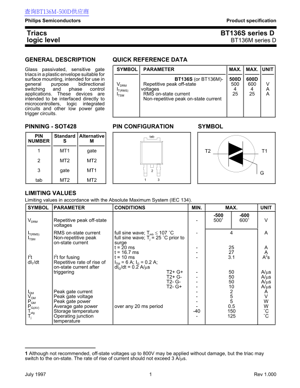
Page 1 Text Content
查询BT136M-500D供应商 Philips Semiconductors Product specification
Triacs BT136S series D logic level BT136M series D
GENERAL DESCRIPTION QUICK REFERENCE DATA Glass passivated, sensitive gate SYMBOL PARAMETER MAX. MAX. UNIT triacs in plastic envelope suitable for surface mounting, intended for use in BT136S (or BT136M)- 500D 600D
general purpose bidirectional VDRM Repetitive peak off-state 500
switching and phase control IT(RMS) voltages applications. These devices are ITSM RMS on-state current intended to be interfaced directly to Non-repetitive peak on-state current microcontrollers, logic integrated circuits and other low power gate trigger circuits.
PINNING - SOT428 PIN CONFIGURATION SYMBOL PIN Standard Alternative tab NUMBER
MT1 gate T1T2
MT2 MT2 gate MT1
tab MT2 MT2
LIMITING VALUES Limiting values in accordance with the Absolute Maximum System (IEC 134). SYMBOL PARAMETER CONDITIONS MIN. MAX. UNIT
VDRM Repetitive peak off-state
voltages
IT(RMS) RMS on-state current full sine wave; Tmb ≤ 107 ˚C ITSM Non-repetitive peak full sine wave; Tj = 25 ˚C prior to
on-state current surge
t = 20 ms t = 16.7 ms
I2t I2t for fusing t = 10 ms 3.1 A2s d IT/dt Repetitive rate of rise of ITM = 6 A; IG = 0.2 A;
on-state current after d IG/dt = 0.2 A/µs triggering T2+ G+ A/µs
IGM Peak gate current VGM Peak gate voltage PGM Peak gate power PG(AV) Average gate power over any 20 ms period 0.5 Tstg Storage temperature -40 ˚C Tj Operating junction ˚C
temperature
1 Although not recommended, off-state voltages up to 800V may be applied without damage, but the triac may switch to the on-state. The rate of rise of current should not exceed 3 A/µs.
July 1997 Rev 1.000
Page Summary Contents For Philips Semiconductors BT136S Series Data Sheet
Manual Details
| Brand | Philips |
|---|---|
| Pages | 6 |
| File Size | 52.34 KB |
| Published | June 16, 2026 |
Enter the captcha to get the download link:

Frequently Asked Questions
What is the maximum continuous operational current (I_RMS)?
The device is rated for up to 25 A at full sine wave when the temperature is less than or equal to 107°C.
Are there restrictions on applying high off-state voltages?
Although off-state voltages up to 800V can be applied without damage, this is not recommended as it may cause the triac to switch on undesirably.
What voltage/timing limits are crucial during triggering?
The rate of rise of current (dI/dt) should generally not exceed 3 A/μs, and the junction temperature limit is 125°C.