Page 1
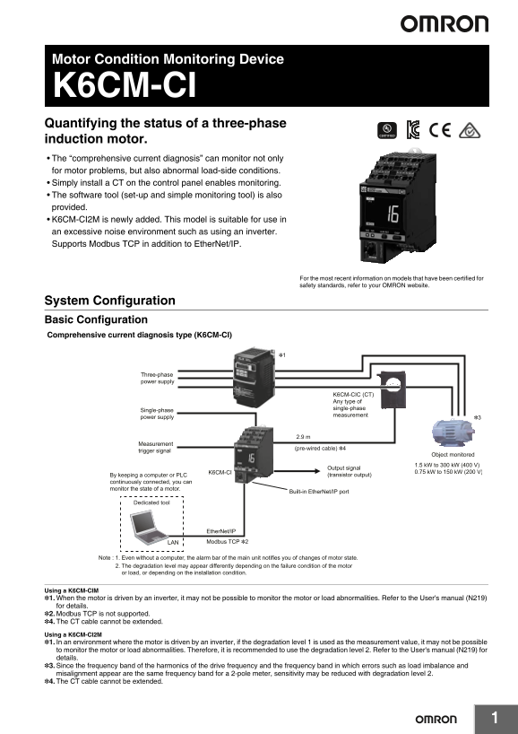
Motor Condition Monitoring Device K6CM-CI Quantifying the status of a three-phase induction motor. The “comprehensive current diagnosis” can monitor not only for motor problems, but also abnormal load...
Page 2
K6CM-CI Ordering Information List of Models Degradation level/ Monitoring type Degradation level 2 Power supply voltage Model Degradation level 1 100 to 240 VAC K6CM-CI2MA-EIP Comprehensive current 24...
Page 3
K6CM-CI Ratings and Specifications List of Models Ratings K6CM-@@MA: 100 to 240 VAC, 50/60 Hz Power supply voltage K6CM-@@MD: 24 VAC, 50/60 Hz, 24 VDC Power Allowable operating voltage range 85% to 11...
Page 4
K6CM-CI Characteristics Current Rating 5 A: 1.00 to 5.00 A Rating 25 A: 5.0 to 25.0 A Rating 100 A: 20.0 to 100.0 A Rating 200 A: 40.0 to 200.0 A Measurement range Rating 400 A: 80.0 to 400.0 A Rating...
Page 5
K6CM-CI CT Ratings and Specifications Model K6CM-CICB005 K6CM-CICB025 K6CM-CICB100 K6CM-CICB200 K6CM-CICB400 K6CM-CICB600 Item Construction Indoor split type Primary-side rated current 5 A 25 A 100 A ...
Page 6
K6CM-CI Connection Diagram Terminal Diagram (Main Unit) K6CM- CI M A -EIP Sensor input (1) Power voltage CT input A: 100 to 240 V AC D: 24 V AC/DC K6CM-CIC (CT) White Black (No polarity) External trig...
Page 7
K6CM-CI Nomenclature Push-in Plus terminal Push-in Plus terminal · Unit power supply · Sensor input · External trigger input Alarm bar 2D code Measurement value units (measurement type) Current value,...
Page 8
K6CM-CI Dimensions (Unit: mm) List of Models K6CM-CI CT K6CM-CICB005 K6CM-CICB025 CT Through-hole CT Through-hole Dimensions Dimensions K6CM-CICB100 K6CM-CICB200 CT Through-hole CT Through-hole Dimens...
Page 9
K6CM-CI K6CM-CICB400 Cable supplied with CT K6CM-CICB600 Product side CT side Contraction tube CT Through-hole Dimensions The cable supplied with the CT is shipped in the connected state.
Page 10
K6CM-CI Comprehensive Current Diagnosis Type Technical Data (Reference) Use one CT per motor to detect current flowing into the motor. Select a CT that matches the motor capacity. Maximum Applicable m...
Page 11
K6CM-CI List of Parameters Setting values Parameter Content Degradation level alarm threshold value (Critical and Warning) 0 to 9999 CT rating 5 A: 00.00 to 99.99 A Current alarm threshold value (Crit...
Page 12
K6CM-CI Measured values / Status data Parameter Content Degradation level of the motor calculated by measuring the current Degradation level (Present value, MIN, MAX) including the high-frequency comp...
Page 13
Motor Condition Monitoring Device K6CM-VB Quantifying the status of a three-phase induction motor. Bearing failures can be detected quickly. Using manual allows you to set the default values for the a...
Page 14
K6CM-VB Ordering Information List of Models Monitoring type Power supply voltage Model 100 to 240 VAC K6CM-VBMA-EIP Vibration & temperature type 24 VAC/VDC K6CM-VBMD-EIP Input part Vibration &...
Page 15
K6CM-VB Ether Net/IP communications cable recommended parts Use a Category 5 or higher STP cable (shielded twisted pair cable). Cable with Connectors Recommended Item Cable length (m) Model manufactur...
Page 16
K6CM-VB Ratings and Specifications List of Models Ratings K6CM-@@MA: 100 to 240 VAC, 50/60 Hz Power supply voltage K6CM-@@MD: 24 VAC, 50/60 Hz, 24 VDC Power Allowable operating voltage range 85% to 11...
Page 17
K6CM-VB Characteristics Acceleration: 0.05 to 9.99 G, Velocity: 0.90 to 45.00 mm/s, Measurement range Motor temperature: 0 to 80°C, Differential temperature: 0 to 80°C Measurement Acceleration ±3 d B±...
Page 18
K6CM-VB Input part Vibration & temperature sensor Ratings Item Model K6CM-VBS1 Power supply voltage Supplied from K6CM-VB Sensor head Max. acceleration 10 G Pre-amplifier: -10 to +55°C (with no co...
Page 19
K6CM-VB Motor condition monitoring Tool (Software included with main unit) Operating Environment Element Specification Supported OS Windows 7, Windows 8.1, Windows 10 (32 bit/64 bit) (Japanese/English...
Page 20
K6CM-VB Connection Diagram Terminal Diagram (Main Unit) K6CM- VB M A -EIP (1) (2) (1) Sensor input (2) Power voltage VB: Vibration and A: 100 to 240 V AC D: 24 V AC/DC temperature sensor input K6CM-VB...
Page 21
K6CM-VB Nomenclature Push-in Plus terminal Push-in Plus terminal · Unit power supply · Sensor input · External trigger input Alarm bar 2D code Measurement value units (measurement type) Current value,...
Page 22
K6CM-VB Dimensions (Unit: mm) List of Models K6CM-VB Vibration & temperature sensor K6CM-VBS1 Pre-amplifier M12 (smart click connector) M12 (smart click connector) Sensor head Mounting hole dimens...
Page 23
K6CM-VB Vibration & Temperature Type: Technical Data Pairing of sensor head and pre-amplifier The sensor head and the pre-amplifier are calibrated and inspected as a set at the factory shipment. B...
Page 24
K6CM-VB List of Parameters Setting values Parameter Content Acceleration alarm threshold value (Critical and Warning) 0.00 to 99.99 G Velocity alarm threshold value (Critical and Warning) 0.00 to 99.9...
Page 25
K6CM-VB Measured values / Status data Parameter Content Acceleration (Present value, MIN, MAX) 0.00 to 9.99 G Velocity (Present value, MIN, MAX) 0.00 to 45.00 mm/s Motor temperature 0 to 80°C (32 to 1...
Page 27
Motor Condition Monitoring Device K6CM-IS Quantifying the status of a three-phase induction motor. ZCT (IRT) is compatible with UL Recognition The “insulation resistance” can be always monitored in li...
Page 28
K6CM-IS System Configuration Basic Configuration Insulation resistance type (K6CM-IS) Three-phase, three-conductor, S-phase ground (Measurement is also Inverter *1 possible without an inverter) Invert...
Page 29
K6CM-IS Ordering Information List of Models Monitoring type Power supply voltage Model 100 to 240 VAC K6CM-ISMA-EIP Insulation resistance type 24 VAC/VDC K6CM-ISMD-EIP ZCT (IRT) (Order separately) Thr...
Page 30
K6CM-IS Ratings and Specifications List of Models Ratings K6CM-@@MA: 100 to 240 VAC, 50/60 Hz Power supply voltage K6CM-@@MD: 24 VAC, 50/60 Hz, 24 VDC Power Allowable operating voltage range 85% to 11...
Page 31
K6CM-IS Characteristics Insulation resistance: 0.000 M to 1.000 MΩ, Measurement range Leakage current: 0.0 m A to 200.0 m A Measurement ±35% rdg±2 digit (when the insulation resistance is 0.2 MΩ max.)...
Page 32
K6CM-IS ZCT (IRT) Ratings and Specifications Item Model K6CM-ISZBI52 Construction Indoor split type Rated path current 300 A Through hole dia. 52 mm dia. Rated voltage 200 to 480 VAC, 50 Hz/60 Hz thre...
Page 33
K6CM-IS Connection Diagram Terminal Diagram (Main Unit) K6CM- IS M A -EIP (1) (2) (1) Sensor input (2) Power voltage IS: ZCT (IRT) input A: 100 to 240 V AC D: 24 V AC/DC K6CM-ISZ (ZCT(IRT)) white Red ...
Page 34
K6CM-IS Nomenclature Push-in Plus terminal Push-in Plus terminal · Unit power supply · Sensor input · External trigger input Alarm bar 2D code Measurement value units (measurement type) Current value,...
Page 35
K6CM-IS Dimensions (Unit: mm) List of Models K6CM-IS ZCT (IRT) Indoor split type (159) K6CM-ISZBI52 (150) 52 dia. Four, M4 Two, M5 Mounting hole dimensions Four, M6
Page 36
K6CM-IS Insulation Resistance Type Technical Data (Reference) Method of measuring the value on the insulation resistance meter Leakage current includes two types, namely capacitive leakage current (Io...
Page 37
K6CM-IS List of Parameters Setting values Parameter Content Insulation resistance alarm threshold value (Critical and Warning) 0.000 to 9.999 MΩ Sets the IP address of the main unit. Main unit IP addr...
Page 38
K6CM-IS Measured values / Status data Parameter Content Insulation resistance (Present value, MIN, MAX) 0.000 to 1.000 MΩ Leakage current Ior (Present value, MIN, MAX) 0.0 to 200.0 m A Leakage current...
Page 39
Terms and Conditions Agreement Read and understand this catalog. Please read and understand this catalog before purchasing the products. Please consult your OMRON representative if you have any questi...
Page 40
KC Mark 표준 준수 Windows is either a registered trademark or trademark of Microsoft Corporation in the United States and/or other countries. Ether Net/IPTM is a trademark of ODVA. Modbus is a registered ...