OMRON Power Other Measuring & Monitoring Relay K8AB Series K8AB-VS Measuring & Monitoring Relay Instruction Manual
Summary
This industrial monitoring relay controller is engineered for robust and reliable performance in demanding electrical environments. The comprehensive manual provides essential guidance covering everything from physical DIN rail installation and detailed terminal wiring to operational parameters and rigorous safety standards. It details system integration, voltage settings, and required precautionary measures. Designed specifically for qualified electrical engineers and technicians, this guide ensures safe, compliant, and expert-level deployment of the high-reliability unit in industrial applications.
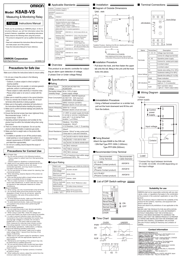
Page 1 Text Content
Applicable Standards Installation Terminal Connections
Installation Installation Category Ⅲ, ●Diagram of Outside Dimensions environment Ponllution Degree 2
Application Unit : mm
Model K8AB-VS EN60255-5/-6
Standard
Safety
Measuring & Monitoring Relay EN60664-1 V1 V2 V3
Standard
(EMI) EN61326+A1 Industrial applications Volume Settings
Terminal interference wave voltage SV
LED Indications PWR
English Instructions Manual CISPR11 Group1, Class A : CISPR16-1/-2
Electromagnetic interference wave
CISPR11 Group1, Class A : CISPR16-1/-2 RY
Thank you for purchasing an OMRON pridyct. In this In- (EMS) EN61326+A1 Industrial applications
structions Manual, you will find information about this Electrostatic
EN61000-4-2 : 4k V(Contact) 8k V(In air)
discharge
product’s features, capabilities, and operating instructions.
Please observe the following when using this product. Radiating radio- EN61000-4-3 : 10V/m 1k Hz Sine Wave frequency electr Amplitude Modulation
・This product is designed for use by qualified electrical engi
EMC -omagnetic field (80MHz to 1GHz)
neer. A1 A2
EN61000-4-4 : 2k V(Power Line)
・Read and understand this Instructions Manual thoroughly, Burst
1k V(I/O Signal line)
and make proper use of this product. Terminals
EN61000-4-5 : 1k V with line (Power Line) *Installation Procedure : Attaching to the DIN rail or attaching with front screws
Surge
・Keep this Instructions Manual for future reference. 2k V with ground (Power Line) *Measurements for attachment with front screws
Conducted RF EN61000-4-6 : 3V(0.15 to 80MHz)
Name Terminal Name Description
Power frequency magnetic field EN61000-4-8 : 30A/m V1, V2, V3 Voltage input terminals
immunity 2-M 4 screw or 2-φ 4.5 opening
Common for voltage input terminals
EN61000-4-11 : 0.5 Cycle, *When attaching wih front screws, draw out hooks
Voltage dip/Short
0.180°each polarity 100% on the bottom of the product to the left and right sides.
interruptions A1, A2 Operative power supply
(Rated Voltage)
Terminals
All Rights Reservedc 9419059-7 E Common for contact point output
●Installation Procedure
b-contact output
Overview
・Pull down the hook, and then fasten the upper
a-contact output
Precautions for Safe Use This product is an electric controller for output- tab onto the rail, fitting in the unit until the hook
SV Operate value setting (10 to 100%)
ting an alarm upon detection of voltage. locks into place.
Make sure to follow the instructions below to ensure safety. HYS. Hysteresis setting (5 to 50%)
Volume Settings
[1-phase Over or Under voltage Relay]
Operate time setting (0.1 to 30s)
1. Do not use or keep this product in the following
PWR Power indication
environments. Specifications
Relay output status
・Outdoors, or places subject to direct sunlight or RY
LED Indications Light-on 11-14 conduction
wearing weather. ●Rating
・Places where dust, iron powder, or corrosive gases(in Alarm operation status
Power Supply AC/DC24V,AC100/115V, ALM
Light-on = Alarm output status
particular, sulfuric or ammonia gas) exist. Voltage AC200/230V ・Places subject to static electricity or inductive noise.
Permissible Voltage 85 to 110% of rated
・Places where water or oil come in contact with the Wiring Diagram
Variability Range power-supply voltage
product.
AC/DC24V : 5VA/1W maximum
2. Make sure to install this product in the correct direction. Power Consumption 1-phase
AC100/115V : 4VA maximum
3. There is a remote risk of electric shock. Do not touch AC200/230V : 5VA maximum power supply
●Uninstallation Procedure
terminals while electricity is being supplied.
20MΩ minimum (at 500V)
Dielectric Resistance ・Using a flathead screwdriver or a similar tool,
4. Make sure to thoroughly understand all instructions in
Between electric circuit and case
the Instructions Manual before handling this product. pull out the hook downward and lift the unit
Dielectric Withstanding 2000V for 1 minute
5. Make sure to confirm terminal makings and polarity for
Voltage Between electric circuit and case from the bottom.
Control
correct wiring.
±1,500V on power-supply terminals power
6. Ensure that terminal screws have been tightened firmly.
in normal or common mode(Square supply
Recommended torque : 0.49 N・m
Noise Immunity
wave with 1 ns at rearing Pulse
Assured torque : 0.59 N・m
duration 1μs/100ns)
7. Operating ambient temperature and humidity for this
product must be within the indicated rating when using Vibrations : 10 to 55Hz,
this product. Vibration Resistance Acceleration : 50m/s2 ,
8. There is a remote risk of explosion. Do not use this X,Y,Z Directions : 5 min × 10 scanning Input voltage
product where flammable or explosive gas exists. 150m/s2 9. Make sure that no weight rests on the product after Shock Resistance (however, 100m/s2 at relay contact point) installation. 3 times each in 3 axis and 6 directions 10. To enable an operator to turn off this product easily,
-VS1 AC/DC 6-60/10-100/30-300m V
install switches or circuit breakers that conform to ●Fixing Bracket
Input Range Ry
-VS2 AC/DC 1-10/3-30/15-150V
relevant requirements of IEC60947-1 and IEC60947-3, Contactor
Attach the type K8AB to the DIN rail.
and label them appropriately. -VS3 AC/DC 20-200/30-300/60-600V
11. Do not turn a setting volume beyond the scope of ・DIN Rail Type PFP-100N (1,000mm)
-VS1 9kΩ minimum
movement. Type PFP-50N (500mm)
Input Impedance
-VS2 100kΩ minimum
Precautions for Correct Use
-VS3 1MΩ minimum ●Recommended Crimp Terminal
●For Proper Use
115% of maximum input within range
(1)Do not use the product in the following locations. Overload Capacity Load
Recommended Recommended
(continuous)/125%, 10s
・Places subject to radiant heat from heat generating
Crimp Terminal Cable Diameter
devices. ・Places subject to vibrations or physical shocks. * Connect the input between terminals
●Output Rating AI 1,5-8BK
(2)Make sure to use setting values appropriate for the AWG#16
V1-COM, V2-COM, V3-COM depending on
controlled object. Failure to do so can cause (Phoenix Contact product)
Rated Load Resistance Load : AC250V 6A, DC30V 6A the input voltage
unintended operation, and may result in accident or
AI 1-8RD
corruption of the product. AWG#18
AC250V, DC30VMaximum Contact
(3)Do not use thinner or similar solvent for cleaning. Use Point Voltage (Phoenix Contact product)
commercial alcohol.
(4)When discarding, properly dispose of the product as AI 0,75-8GY
AC6A, DC6AMaximum Contact
Point Current AWG#18
industrial waste. (Phoenix Contact product)
Relay
(5)Only use this product within a board whose structure
Output 1500VA, 180WMaximum Opening and
allows no possibility for fire to escape. Closing Capacity (6)This is a class A product. In residential areas it may
List of DIP Switch settings
cause radio interference, in which case the user may DC5V, 10m A *Reference value Minimum Applicable
be required to take adequate measures to reduce Load (P Level)
interference. 10 million times minimum Mechanical Life
●About Installation
Electrical Life Suitability for use
(1)When wiring, use only recommended crimp terminals. Make 50 thousand time,
(Ambient temperature
(2)Do not block areas around the product for proper Break 30 thousand times
condition : +20℃) OMRON shall not be responsible conformity with any stan
dissipation of heat. (If you do not secure space for T1=5s
-dards, codes, or regulations that apply to the combination
heat dissipation, life cycle of the product will be
T1=1s of the products in the customer's application or use of the
compromised.)
product.
(3)To avoid electrical shocks, make sure that power is Auto Reset
not supplied to the product while wiring. Take all necessary steps to determine the suitability of the
Manual Reset product for the systems, machines, and equipment with
(4)To avoid electrical shocks, make sure that power is
not supplied to the product when performing DIP : ON which it will be used.
Normal Close
switch settings. Know and observe all prohibitions of use applicable to this
: OFF
●Noise Conutermeasures Normal Open product.
(1)Do not install the product near devices generating NEVER USE THE PRODUCTS FOR AN APPLICATION
UNDER
strong high frequency waves or surges. INVOLVING SERIOUS RISK TO LIFE OR PROPERTY (2)When using a noise filter, check the voltage and OVER WITHOUT ENSURING THAT THE SYSTEM AS A current and install it as close to the product as possible.
WHOLE HAS BEEN DESIGNED TO ADDRESS THE
(3)In order to prevent inductive noise, wire the lines
RISKS, AND THAT THE OMRON PRODUCT IS PROPER
connected to the product separately from power lines
Time Chart -LY RATED AND INSTALLED FOR THE INTENDED USE
carrying high voltages or currents. Do not wire in
WITHIN THE OVERALL EQUIPMENT OR SYSTEM.
parallel with or on the same cable as power lines.
OVER UNDER See also Product catalog for Warranty and Limitation of
Other measures for reducing noise include running
Liability.
lines along separate ducts and using shield lines. PWR ●To avoid faulty operations, malfunctions, or failure,
observe the following operating instructions.
Contact Information
(1)When turning on the power, make sure to realize
rated voltage within 1 second from the time of first SV
OMRON ELECTRONICS LLC.
supply of electricity. One Commerce Drive Schaumburg, IL 60173-5302 U.S.A
RY Phone: 1-847-843-7900 Fax: 1-847-843-7787
(2)Make sure to use power supply for operations, inputs,
OMRON CANADA INC.
and transformer with the appropriate capacity and 885 Milner Avenue Scarborough, Ontario M1B 5V8, CANADA
ALM Phone: 1-416-286-6465 Fax: 1-416-286-6648
rated burden.
T1 OMRON EUROPE B.V.
(3)Maintenance and handling of this product may only Wegalaan 67-69, 2132 JD Hoofddorp The Netherlands
be performed by qualified personnel. Phone: 31-23-56-81-300 Fax: 31-23-56-81-388 V3V2 A1 14V1 OMRON ELECTRONICS PTY.LTD.
(4)Do not use this product with circuits that have distor
71 Epping Road, North Ryde, Sydney, N.S.W 2113, Australia
-ted input wave forms. Distortion in wave forms will Phone: 61-2-9878-6377 Fax: 61-2-9878-6981
result in errors. OMRON ASIA-PACIFIC PTE. LTD. No.438A Alexandra Road #05-05/08(Lobby 2), Alexandra
(5)Using this product for thyrister controls or inverters Technopark, Singapore 119967
wil result in errors. Phone: 65-6835-3011 Fax: 65-6835-2711 OMRON CORPORATION.
(6)When setting the volume, adjust the control from the A2
Shiokoji Horikawa, Shimogyo-ku, KYOTO, 600-8530 Japan minimum side to the maximum side. Phone: 81-75-344-7109 Fax: 81-75-344-7149
Page Summary Contents For OMRON Power Other Measuring & Monitoring Relay K8AB Series K8AB-VS Measuring & Monitoring Relay Instruction Manual
Manual Details
| Brand | Omron |
|---|---|
| Pages | 1 |
| File Size | 64.77 KB |
| Published | June 04, 2026 |
Enter the captcha to get the download link:

Frequently Asked Questions
How should I install this unit?
It can be attached to a DIN rail or mounted using front screws and hooks.
What adverse environments should be avoided?
Do not use it outdoors, in places with direct sunlight, dust, corrosive gases, water, or oil.
What are the standard voltage specs?
The recommended operating input voltage is AC200/230V, allowing for 85 to 110% variability.
What should I do before unplugging it?
Pull down the hook and lift the unit after making sure you have thoroughly understood all instructions in the manual.