OMRON Power Other Motor Condition Monitor K6CM K6CM Motor Condition Monitoring Device Startup Guide
Summary
This comprehensive guide is essential for installing and operating the K6CM Motor Condition Monitoring Device. Designed for industrial technicians and facility managers, it enables advanced monitoring of motor health by diagnosing current flow, detecting vibration/temperature changes, and checking insulation resistance. The manual walks you through crucial steps, including proper sensor selection tailored to your specific motor capacity, system configuration, detailed tool installation, wiring connection processes, and pre-verification checks for reliable, sustained performance.
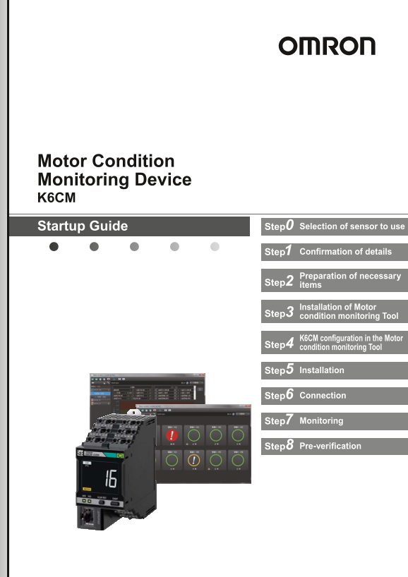
Page 1 Text Content
Motor Condition Monitoring Device K6CM
Startup Guide Step0 Selection of sensor to use
Step1 Confirmation of details
Preparation of necessary
Step2 items
Installation of Motor
Step3 condition monitoring Tool
K6CM configuration in the Motor
Step4 condition monitoring Tool
Step5 Installation
Step6 Connection
Step7 Monitoring
Step8 Pre-verification
Page Summary Contents For OMRON Power Other Motor Condition Monitor K6CM K6CM Motor Condition Monitoring Device Startup Guide
Page 1
Motor Condition Monitoring Device K6CM Startup Guide Step0 Selection of sensor to use Step1 Confirmation of details Preparation of necessary Step2 items Installation of Motor Step3 condition monitorin...
Page 2
Thank you for purchasing this product. This guide explains simple procedures for starting the product, and methods for its operation. For more detailed explanations, please refer to the included Opera...
Page 3
Step1 Confirmation of details K6CM unit Operation Manual (JP/EN, A4 size) LAN port cover IP address label (for IP address input) Tool (Motor condition monitoring Push-in Plus Terminal Blocks Tool) CD-...
Page 4
Step3 Installation of Motor condition monitoring Tool 1 Installing .NET Framework 3.5 SP1 The Motor condition monitoring Tool requires Microsoft .NET Framework 3.5 SP1 to run the program. If .NET Fram...
Page 5
2) Enter “winver”and click [OK].Button. 3) The Windows version is displayed, so confirm. [2] OS media creation Run the downloaded OS media creation tool. Be sure to select "Create installation me...
Page 6
Select the media type to use. When selecting "USB flash drive", be sure to prepare an empty recording medium (USB memory of 8 GB or more, HDD or DVD) without data. At this point, connect the...
Page 7
Since the Explorer screen starts, click the drive icon displayed on the left side of the screen that started up.If the OS media is recognized correctly, the drive containing the following data will be...
Page 8
Enter the following command and press Enter to execute. In the command, "D:" is the drive to which the OS media checked earlier was assigned. Depending on the user environment used. As you c...
Page 9
(4) Check the check box of "Microsoft .NET Framework 3.5.1" and click "OK". 2 Installation Procedures This section shows the procedure for installing a new Motor condition monitori...
Page 10
CAUTION If the following message is displayed, a newer version of the software tool than the launched installer has already been installed on your PC. Therefore, installation is unnecessary. CAUTION I...
Page 11
(2) Select "Japanese" or "English" and click the [Next] Button. The following Dialog Box will be displayed. * After installation, you cannot change the language of the software too...
Page 12
(9) Since a dialog box prompting you to install Win Pcap which is a component of Communications Middleware is displayed, click the [OK] Button. If Win Pcap is already installed, go to step (15). (10) ...
Page 13
(14) From the Motor condition monitoring Tool, select the network card to be used for automatic connection to the K6CM device with the Ethernet cable from the pull-down list and click the [OK] Button....
Page 14
3 PC IP address setting Windows 7 (1) Select [Start] | [Control Panel] | [Network and Sharing Center] | [Change Adapter Settings]. (2) Right-click [Loca Area Connection] and select [Properties]. (3) S...
Page 15
5 Select [Device setting] This configures communications settings between the PC and the K6CM. From the Motor condition monitoring Tool Startup screen, select [Device setting]. The following SYSMAC Ga...
Page 16
Click the LAN card tab, and select the LAN card in the PC to use in communications with K6CM. LAN card configuration example: If there is only one wired LAN port of the PC and the Motor condition moni...
Page 17
The [Preface] wizard screen of the following [Start navigation] Dialog Box is displayed. Click the [Next] Button. The following [Connecting to device] wizard screen will be displayed. Click the [conne...
Page 18
"Connecting" will be displayed on the line between the PC and the device on the following [Connecting to device] wizard screen. When the connection is successful, the following [IP address s...
Page 19
Input parameter settings values into the settings fields, and click the [Next] button. Set in reference to the following table. Settings values may be changed at a later point, however ensure these ar...
Page 20
The following [Motor name setting] wizard screen will be displayed. Input the motor name that the set device is to monitor, then click the [Next] button. The following [Navigating is completed] wizard...
Page 21
This opens the following monitor screen for each motor unit. Click the [Save the project file] button ( ) for the created project to save. 7 Confirm motor status can be monitored The default settings ...
Page 22
Click the ( ) [Start monitoring] button to start monitoring. If communications between the PC and the K6CM are operating normally, then the monitoring status will be displayed. Any devices unable to c...
Page 23
The following [Each motor detailed information] screen will be displayed. To view the [Each device detailed status] screen, click the area outlined in red. The [Each device detailed status] screen wil...
Page 24
Step5 Installation DIN Rail Mounting There is no particular restriction on the mounting direction of the K6CM device, but install it securely in the horizontal or vertical direction as much as possibl...
Page 25
Step6 Connection 1 Power supply connection, external trigger (when required) connection, transistor output connection Connect the unit to the power supply. 100 to 240 VAC or 24 V power supply (by type...
Page 26
2 Sensor connection Install sensors on the motor wiring. Comprehensive current diagnosis type (K6CM-CI) Three-phase power supply K6CM-CIC (CT) Any type of single-phase Single-phase *3 measurement powe...
Page 27
Vibration & temperature monitoring type (K6CM-VB) Inverter *1 (measurement is also possible without an inverter) Three-phase 2.6 m power supply (pre-wired cable) K6CM-VBS1 (pre-amplifier) Connecto...
Page 28
Insulation resistance monitoring type (K6CM-IS) Three-phase, three-conductor, S-phase ground Inverter *2 (measurement is also possible without an inverter) Inverter secondary-side voltage 40 m max. (F...
Page 29
Step8 Pre-verification 0 Preface The K6CM is more effective when multiple parameters are set appropriately. This section covers the particularly important settings. Conduct the pre-verification as fol...
Page 30
2 Recommended parameter settings during verification The software tool is optimal for the pre-verification and makes it easier to set parameters and collect data. A sample data collection program that...
Page 31
5 Threshold levels settings Set the threshold levels using the before and after data collected. ¢K6CM-CI (Comprehensive current diagnosis type) (1) Open the CSV file to graph the results. (2) Set the ...
Page 32
Moving average times • If there is a lot of variation, simply create a moving average in the file and process the average. In the case of a moving average time of 2 (4 times), calculate it per the fig...
Page 33
¢ K6CM-VB (Vibration type) The alarm threshold of acceleration and velocity can be set automatically by entering the motor information to be monitored in the software tool. (1) Click the [Guide for Se...
Page 34
●When setting velocity alarm Velocity monitoring of the K6CM is based on ISO 2372. [1] Select the measured target and capacity. [2] For large-capacity motors (large-sized machines), select the install...
Page 35
Terms and Conditions Agreement Read and understand this catalog. Please read and understand this catalog before purchasing the products. Please consult your OMRON representative if you have any questi...
Page 36
• Windows is either a registered trademark or trademark of Microsoft Corporation in the United States and/or other countries. • Microsoft product screen shot(s) reprinted with permission from Microsof...
Manual Details
| Brand | Omron |
|---|---|
| Pages | 36 |
| File Size | 3.83 MB |
| Published | June 04, 2026 |
59 views
Enter the captcha to get the download link:
