Motorola Semiconductor MC10E151 MC100E151 Data Sheet / Manual
Summary
This datasheet provides comprehensive technical specifications for the MC10E/MC100E151, a high-speed integrated circuit featuring six D-type, master-slave flip-flops with differential outputs. The manual details electrical characteristics, pin layouts, timing diagrams, and operational parameters vital for robust digital design. It is essential reading for hardware engineers and logic designers needing to integrate reliable, dual-clocked data registers into sophisticated, mission-critical electronic systems.
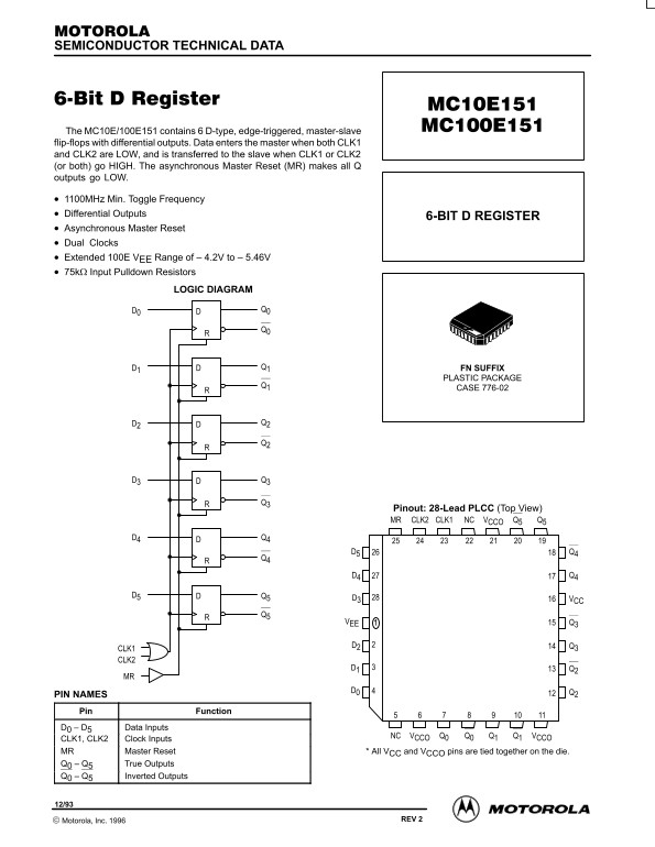
Page 1 Text Content
SEMICONDUCTOR TECHNICAL DATA
The MC10E/100E151 contains 6 D-type, edge-triggered, master-slave flip-flops with differential outputs. Data enters the master when both CLK1 and CLK2 are LOW, and is transferred to the slave when CLK1 or CLK2 (or both) go HIGH. The asynchronous Master Reset (MR) makes all Q outputs go LOW.
1100MHz Min. Toggle Frequency Differential Outputs
6-BIT D REGISTER
Asynchronous Master Reset Dual Clocks Extended 100E VEE Range of – 4.2V to – 5.46V 75kΩ Input Pulldown Resistors
LOGIC DIAGRAM
D1 Q1 FN SUFFIX
PLASTIC PACKAGE
CASE 776-02
Pinout: 28-Lead PLCC (Top View)
Q5VCCONCCLK1CLK2MR Q5
D3 VCC
VEE Q3
CLK1 CLK2
PIN NAMES Pin Function D0 D5 Data Inputs
NC VCCO Q0 Q0 Q1 Q1 VCCO
CLK1, CLK2 Clock Inputs MR Master Reset * All VCC and VCCO pins are tied together on the die. Q0 Q5 True Outputs Q0 Q5 Inverted Outputs
2–1 REV 2 Motorola, Inc. 1996
Page Summary Contents For Motorola Semiconductor MC10E151 MC100E151 Data Sheet / Manual
Manual Details
| Brand | Motorola |
|---|---|
| Pages | 5 |
| File Size | 66.02 KB |
| Published | June 04, 2026 |
Enter the captcha to get the download link:

Frequently Asked Questions
How many D-type flip-flops does this IC contain?
The chip contains 6 D-type, edge-triggered, master-slave flip-flops with differential outputs.
What is the maximum specified toggle frequency?
The documented Max. Toggle Frequency ranges from 1100 MHz to 1400 MHz depending on the condition.
Can this chip be used in medical implants or life support systems?
No. Motorola products are not intended or authorized for use as components in surgical implant systems or life-sustaining applications.
What is required before integrating this IC into a customer's system?
All operating parameters, including "Typicals," must be validated for each customer application by the customer’s technical experts.