Motorola MC74AC253 MC74ACT253 Data Sheet / Manual
Summary
This dual 4-input multiplexer is engineered for selection and switching tasks within complex digital systems. It features two independent 4-input sections, each offering 3-state outputs controlled by individual Output Enable inputs, making it ideal for bus-oriented interfaces that require high impedance (High Z) states. The accompanying manual provides comprehensive details on its functional operation, including truth tables, logic diagrams, maximum ratings across environmental ranges, and essential DC characteristics needed for robust circuit design. It is designed specifically for electrical engineers and hardware designers building reliable digital signal processing circuitry.
Page 1 Text Content
查询MC74AC253供应商
DUAL 4-INPUT MULTIPLEXER WITH 3-STATE OUTPUTS
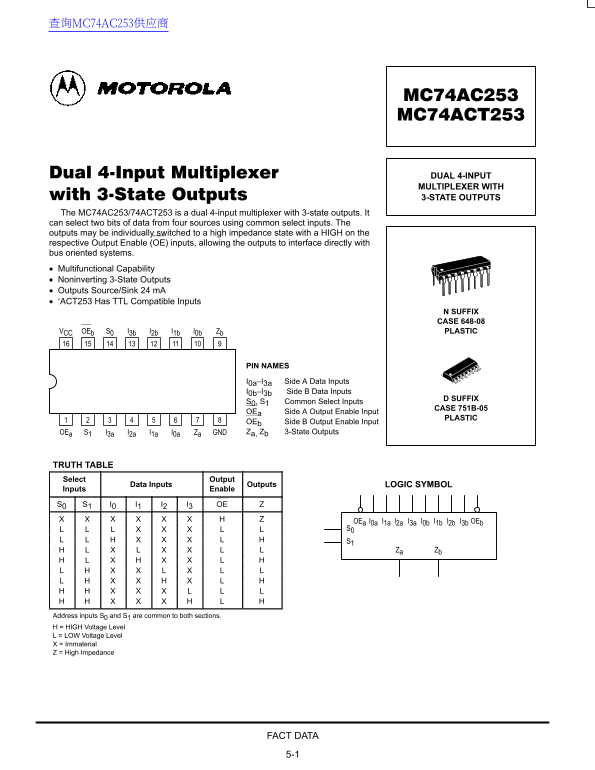
The MC74AC253/74ACT253 is a dual 4-input multiplexer with 3-state outputs. It can select two bits of data from four sources using common select inputs. The outputs may be individually switched to a high impedance state with a HIGH on the respective Output Enable (OE) inputs, allowing the outputs to interface directly with bus oriented systems. Multifunctional Capability Noninverting 3-State Outputs Outputs Source/Sink 24 m A ′ACT253 Has TTL Compatible Inputs
N SUFFIX CASE 648-08 VCC OEb S0 I3b I2b I1b I0b Zb PLASTIC
PIN NAMES I0a–I3a Side A Data Inputs I0b–I3b Side B Data Inputs
D SUFFIX
S0, S1 Common Select Inputs
CASE 751B-05
OEa Side A Output Enable Input
PLASTIC
OEb Side B Output Enable Input OEa S1 I3a I2a I1a I0a Za GND Za, Zb 3-State Outputs
TRUTH TABLE Select Output
Data Inputs Outputs LOGIC SYMBOL
Inputs Enable S0 S1 I0 I1 I2 I3 OE
OEa I0a I1a I2a I3a I0b I1b I2b I3b OEb
Za Zb
Address inputs S0 and S1 are common to both sections. H = HIGH Voltage Level L = LOW Voltage Level X = Immaterial Z = High Impedance
FACT DATA 5-1
Page Summary Contents For Motorola MC74AC253 MC74ACT253 Data Sheet / Manual
Manual Details
| Brand | Motorola |
|---|---|
| Pages | 8 |
| File Size | 181.64 KB |
| Published | June 06, 2026 |
Enter the captcha to get the download link:

Frequently Asked Questions
What is the primary function of the MC74AC253?
It functions as a dual 4-input multiplexer capable of selecting two bits of data from four sources.
How are the outputs managed to prevent electrical conflicts?
Individual Output Enable (OE) inputs can force the output into a high impedance state, preventing potential overcurrents.
What is the recommended operating temperature range for this device?
The recommended operating ambient temperature range is from –40°C to 85°C.
Can I use this integrated circuit in life-support medical devices?
No, it is not authorized or designed for use in surgical implants or applications intended to support or sustain life.