MOTOROLA MBRD320 330 340 350 360 DATA SHEET
Summary
Discover high-performance MBRD rectifiers designed for advanced power electronics applications, including switch-mode power supplies and inverters. This manual provides comprehensive technical data covering crucial electrical characteristics, thermal guidelines, packaging specifications, and performance details. It is essential reading for electrical engineers and designers requiring reliable, state-of-the-art diodes capable of supporting demanding switching and inductive circuits.
Page 1 Text Content
查询MBRD320/D供应商
Order this document
SEMICONDUCTOR TECHNICAL DATA by MBRD320/D
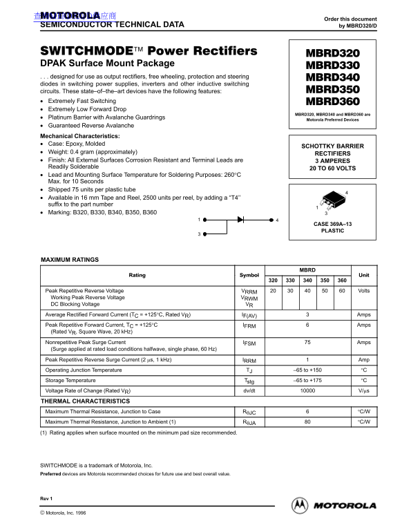
DPAK Surface Mount Package designed for use as output rectifiers, free wheeling, protection and steering diodes in switching power supplies, inverters and other inductive switching circuits. These state–of–the–art devices have the following features: Extremely Fast Switching Extremely Low Forward Drop
MBRD320, MBRD340 and MBRD360 are
Platinum Barrier with Avalanche Guardrings
Motorola Preferred Devices
Guaranteed Reverse Avalanche Mechanical Characteristics: Case: Epoxy, Molded
SCHOTTKY BARRIER
Weight: 0.4 gram (approximately)
RECTIFIERS
Finish: All External Surfaces Corrosion Resistant and Terminal Leads are 3 AMPERES Readily Solderable
20 TO 60 VOLTS
Lead and Mounting Surface Temperature for Soldering Purposes: 260°C Max. for 10 Seconds Shipped 75 units per plastic tube Available in 16 mm Tape and Reel, 2500 units per reel, by adding a “T4’’ suffix to the part number Marking: B320, B330, B340, B350, B360
CASE 369A–13 PLASTIC
MAXIMUM RATINGS
Rating Symbol Unit
Peak Repetitive Reverse Voltage VRRM Volts Working Peak Reverse Voltage VRWM DC Blocking Voltage VR Average Rectified Forward Current (TC = +125°C, Rated VR) IF(AV) Amps Peak Repetitive Forward Current, TC = +125°C IFRM Amps (Rated VR, Square Wave, 20 k Hz) Nonrepetitive Peak Surge Current IFSM Amps (Surge applied at rated load conditions halfwave, single phase, 60 Hz) Peak Repetitive Reverse Surge Current (2 µs, 1 k Hz) IRRM Amp Operating Junction Temperature TJ –65 to +150 °C Storage Temperature Tstg –65 to +175 °C Voltage Rate of Change (Rated VR) dv/dt V/µs THERMAL CHARACTERISTICS Maximum Thermal Resistance, Junction to Case RθJC °C/W Maximum Thermal Resistance, Junction to Ambient (1) RθJA °C/W
(1) Rating applies when surface mounted on the minimum pad size recommended.
SWITCHMODE is a trademark of Motorola, Inc. Preferred devices are Motorola recommended choices for future use and best overall value.
Rev 1
1Rectifier Device Data
Motorola, Inc. 1996
Page Summary Contents For MOTOROLA MBRD320 330 340 350 360 DATA SHEET
Manual Details
| Brand | Motorola |
|---|---|
| Pages | 4 |
| File Size | 94.68 KB |
| Published | June 04, 2026 |
Enter the captcha to get the download link:
