Motorola LP2950 LP2951 Data Sheet
Summary
The LP2950 and LP2951 are highly efficient micropower voltage regulators designed to maximize battery life in portable electronics. Featuring extremely low input–to–output voltage differentials and quiescent bias current, these devices reliably supply over 100 mA while protecting against thermal and internal current issues. The advanced LP2951 model further offers enhanced functionality, including programmable output voltage (1.25V–29V), an error signaling output, and a shutdown input. This manual provides comprehensive specifications for integrating these power-saving regulators into demanding consumer, industrial, and computing equipment.
Page 1 Text Content
查询LP2950/D供应商
Order this document by LP2950/D
MICROPOWER The LP2950 and LP2951 are micropower voltage regulators that are LOW DROPOUT
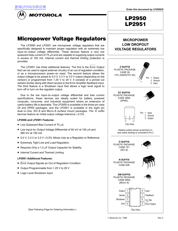
specifically designed to maintain proper regulation with an extremely low VOLTAGE REGULATORS input–to–output voltage differential. These devices feature a very low quiescent bias current of 75 µA and are capable of supplying output currents in excess of 100 m A. Internal current and thermal limiting protection is provided.
The LP2951 has three additional features. The first is the Error Output Z SUFFIX PLASTIC PACKAGE
that can be used to signal external circuitry of an out of regulation condition,
CASE 29
or as a microprocessor power–on reset. The second feature allows the
(TO–226AA/TO–92)
output voltage to be preset to 5.0 V, 3.3 V or 3.0 V output (depending on the
Pin: 1. Output
version) or programmed from 1.25 V to 29 V. It consists of a pinned out
2. Ground
resistor divider along with direct access to the Error Amplifier feedback input. 3. Input The third feature is a Shutdown input that allows a logic level signal to turn–off or turn–on the regulator output.
DT SUFFIX
Due to the low input–to–output voltage differential and bias current PLASTIC PACKAGE
specifications, these devices are ideally suited for battery powered CASE 369A (DPAK)
computer, consumer, and industrial equipment where an extension of useful battery life is desirable. The LP2950 is available in the three pin case 29 and DPAK packages, and the LP2951 is available in the eight pin dual–in–line, SO–8 and Micro–8 surface mount packages. The ‘A’ suffix
Pin: 1. Input
devices feature an initial output voltage tolerance ± 0.5%.
2. Ground 3. Output
LP2950 and LP2951 Features:
(Top View)
Low Quiescent Bias Current of 75 µA Low Input–to–Output Voltage Differential of 50 m V at 100 µA and Heatsink surface (shown as terminal 4 in
380 m V at 100 m A case outline drawing) is connected to Pin 2.
5.0 V, 3.3 V or 3.0 V ±0.5% Allows Use as a Regulator or Reference
D SUFFIX
Extremely Tight Line and Load Regulation
PLASTIC PACKAGE Requires Only a 1.0 µF Output Capacitor for Stability CASE 751 (SO–8)
Internal Current and Thermal Limiting
LP2951 Additional Features:
N SUFFIX PLASTIC PACKAGE
Error Output Signals an Out of Regulation Condition
CASE 626
Output Programmable from 1.25 V to 29 V Logic Level Shutdown Input
DM SUFFIX PLASTIC PACKAGE CASE 846A (Micro–8)
Output Input
Sense Feedback
Shutdown
VO Tap
Gnd Error Output
(See Following Page for Ordering Information.) (Top View)
Motorola, Inc. 1996 Rev 4
1MOTOROLA ANALOG IC DEVICE DATA
Page Summary Contents For Motorola LP2950 LP2951 Data Sheet
Manual Details
| Brand | Motorola |
|---|---|
| Pages | 16 |
| File Size | 255.35 KB |
| Published | May 29, 2026 |
Enter the captcha to get the download link:

Frequently Asked Questions
What makes these regulators suitable for battery-powered equipment?
They feature a very low quiescent bias current of 75 μA and maintain proper regulation with an extremely low input–to–output voltage differential.
How do I ensure stable operation of the regulator output?
Stability requires only a 1.0 μF Output Capacitor.
What functionality does the LP2951 have that the LP2950 lacks?
The LP2951 includes an Error Output for out-of-regulation signaling, programmable voltage (1.25V to 29V), and a digital Shutdown input.