MOTOROLA LM358, LM258, LM2904, LM2904V Dual Low Power Operational Amplifiers Owner's Manual - User Guide
Summary
Discover versatile, low-power dual operational amplifiers designed for robust analog circuit design. These ICs support single and split supply operations (e.g., 3V to 32V) while maintaining an extended common mode input range, eliminating complex biasing needs. The accompanying manual provides comprehensive technical data sheets, detailed electrical characteristics, absolute maximum ratings, and performance graphs necessary for professional electronics engineers building reliable systems.
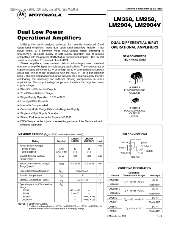
Page 1 Text Content
Order this document by LM358/D
DUAL DIFFERENTIAL INPUT
Utilizing the circuit designs perfected for recently introduced Quad Operational Amplifiers, these dual operational amplifiers feature 1) low OPERATIONAL AMPLIFIERS power drain, 2) a common mode input voltage range extending to ground/VEE, 3) single supply or split supply operation and 4) pinouts
SEMICONDUCTOR
compatible with the popular MC1558 dual operational amplifier. The LM158
series is equivalent to one–half of an LM124. TECHNICAL DATA
These amplifiers have several distinct advantages over standard operational amplifier types in single supply applications. They can operate at supply voltages as low as 3.0 V or as high as 32 V, with quiescent currents about one–fifth of those associated with the MC1741 (on a per amplifier basis). The common mode input range includes the negative supply, thereby eliminating the necessity for external biasing components in many applications. The output voltage range also includes the negative power supply voltage.
N SUFFIX
Short Circuit Protected Outputs
PLASTIC PACKAGE True Differential Input Stage CASE 626
Single Supply Operation: 3.0 V to 32 V Low Input Bias Currents Internally Compensated
D SUFFIX
Common Mode Range Extends to Negative Supply
PLASTIC PACKAGE
Single and Split Supply Operation CASE 751
(SO–8)
Similar Performance to the Popular MC1558 ESD Clamps on the Inputs Increase Ruggedness of the Device without Affecting Operation
MAXIMUM RATINGS (TA = +25°C, unless otherwise noted.) PIN CONNECTIONS
LM258 LM2904 Rating Symbol LM358 LM2904V Unit
Output A VCC
Power Supply Voltages Vdc Output B
Inputs A
Single Supply VCC
Inputs B
Split Supplies VCC, VEE ±16 ±13
VEE/Gnd
Input Differential Voltage VIDR ±32 ±26 Vdc
(Top View)
Range (Note 1)
Input Common Mode Voltage VICR –0.3 to 32 –0.3 to 26 Vdc Range (Note 2)
ORDERING INFORMATION
Output Short Circuit Duration t SC Continuous
Operating
Junction Temperature TJ °C Device Temperature Range Package Storage Temperature Range Tstg –55 to +125 °C LM2904D SO–8
TA = –40° to +105°C
Operating Ambient Temperature TA °C LM2904N Plastic DIP Range
LM2904VD SO–8
LM258 –25 to +85 TA = –40° to +125°C
LM358 0 to +70 LM2904VN Plastic DIP
LM2904 –40 to +105
LM258D SO–8
LM2904V –40 to +125 TA = –25° to +85°C
LM258N Plastic DIP
NOTES: 1. Split Power Supplies.
2. For Supply Voltages less than 32 V for the LM258/358 and 26 V for the LM2904, the LM358D SO–8 absolute maximum input voltage is equal to the supply voltage. TA = 0° to +70°C
LM358N Plastic DIP
Motorola, Inc. 1996 Rev 2
1MOTOROLA ANALOG IC DEVICE DATA
Page Summary Contents For MOTOROLA LM358, LM258, LM2904, LM2904V Dual Low Power Operational Amplifiers Owner's Manual - User Guide
Manual Details
| Brand | Motorola |
|---|---|
| Pages | 8 |
| File Size | 179.12 KB |
| Published | May 27, 2026 |
Enter the captcha to get the download link:

Frequently Asked Questions
What operating temperature range is recommended for continuous operation?
The operating junction temperature (Tj) is rated up to 150 °C, and the device temperature range is typically -55 to +125°C.
Are external components needed to bias the input voltage?
No, because the common mode input range extends down to ground/V-, eliminating the necessity for external biasing components in many applications.
What specific voltages can these dual amplifiers support?
They support single supply operation from 3.0 V up to 32 V, or split supply operation (V and -V).
What safety precautions must be taken when using this device?
These products are not designed for surgical implants or systems intended to support life; misuse requires indemnification against related claims.