# A B C D E F G H I J K L M N O P Q R S T U V W X Y Z

LINEAR TECHNOLOGY - LTM4600HV Data Manual

Summary

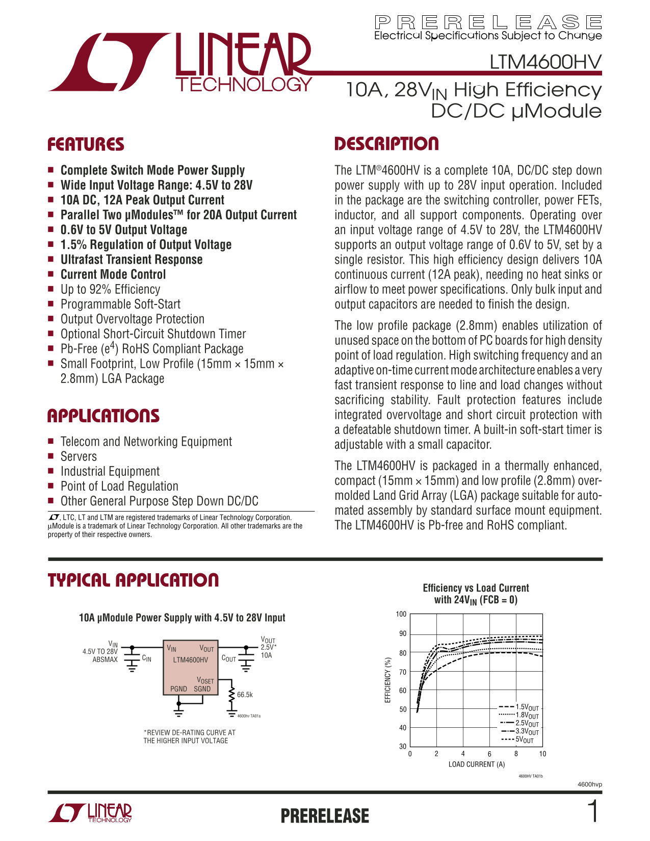
This high-efficiency LTM4600HV is a compact, complete 10A DC/DC step-down switching power module designed for reliable conversion across wide input ranges (4.5V to 28V). It features built-in protection and ultra-fast response in a small LGA footprint. The manual provides detailed electrical specifications, application guidelines, pin configuration tables, and operational characteristics necessary for designers building high-density systems for applications including telecommunications, servers, and general industrial equipment needing point-of-load regulation.
📄 Preview PAGE OF 24

Page 1 Text Content

Electrical Specifications Subject to Change

LTM4600HV

10A, 28VIN High Effi ciency

DC/DC µModule

FEATURES DESCRIPTIO

■ Complete Switch Mode Power Supply The LTM®4600HV is a complete 10A, DC/DC step down ■ Wide Input Voltage Range: 4.5V to 28V power supply with up to 28V input operation. Included ■ 10A DC, 12A Peak Output Current in the package are the switching controller, power FETs, ■ Parallel Two µModules™ for 20A Output Current inductor, and all support components. Operating over ■ 0.6V to 5V Output Voltage an input voltage range of 4.5V to 28V, the LTM4600HV ■ 1.5% Regulation of Output Voltage supports an output voltage range of 0.6V to 5V, set by a ■ Ultrafast Transient Response single resistor. This high effi ciency design delivers 10A ■ Current Mode Control continuous current (12A peak), needing no heat sinks or ■ Up to 92% Effi ciency airfl ow to meet power specifi cations. Only bulk input and ■ Programmable Soft-Start output capacitors are needed to fi nish the design. ■ Output Overvoltage Protection

The low profi le package (2.8mm) enables utilization of

■ Optional Short-Circuit Shutdown Timer

unused space on the bottom of PC boards for high density

■ Pb-Free (e4) Ro HS Compliant Package

point of load regulation. High switching frequency and an

■ Small Footprint, Low Profi le (15mm × 15mm ×

adaptive on-time current mode architecture enables a very

2.8mm) LGA Package

EF FI CI EN CY fast transient response to line and load changes without

sacrifi cing stability. Fault protection features include APPLICATIO integrated overvoltage and short circuit protection with a defeatable shutdown timer. A built-in soft-start timer is

■ Telecom and Networking Equipment

adjustable with a small capacitor.

■ Servers

The LTM4600HV is packaged in a thermally enhanced,

■ Industrial Equipment

compact (15mm × 15mm) and low profi le (2.8mm) over-

■ Point of Load Regulation

molded Land Grid Array (LGA) package suitable for auto-

■ Other General Purpose Step Down DC/DC

mated assembly by standard surface mount equipment.

, LTC, LT and LTM are registered trademarks of Linear Technology Corporation. µModule is a trademark of Linear Technology Corporation. All other trademarks are the The LTM4600HV is Pb-free and Ro HS compliant. property of their respective owners.

TYPICAL APPLICATIO

Effi ciency vs Load Current with 24VIN (FCB = 0)

10A µModule Power Supply with 4.5V to 28V Input

VIN VOUT 2.5V*

4.5V TO 28V

10ACOUT

ABSMAX CIN

LTM4600HV

VOSET

PGND SGND

1.5VOUT 4600hv TA01a 1.8VOUT 2.5VOUT *REVIEW DE-RATING CURVE AT 3.3VOUT THE HIGHER INPUT VOLTAGE 5VOUT

LOAD CURRENT (A)

4600HV TA01b

4600hvp

PRERELEASE

Page Summary Contents For LINEAR TECHNOLOGY - LTM4600HV Data Manual

Page 1 Electrical Specifications Subject to Change LTM4600HV 10A, 28VIN High Effi ciency DC/DC µModule FEATURES DESCRIPTIO ■ Complete Switch Mode Power Supply The LTM®4600HV is a complete 10A, DC/DC step dow...
Page 2 LTM4600HV ABSOLUTE AXI RATI GS PACKAGE/ORDER I FOR ATIO (Note 1) TOP VIEWFCB, EXTVCC, PGOOD, RUN/SS, VOUT .......... ORDER PART –0.3V to 6V NUMBER VIN, SVIN, FADJ ........................................
Page 3 LTM4600HV The ● denotes the specifi cations which apply over the –40°C to 85°C ELECTRICAL CHARACTERISTICS temperature range, otherwise specifi cations are at TA = 25°C, VIN = 12V. Per typical applicat...
Page 4 EF FI CI EN CY EF FI CI EN CY LTM4600HV TYPICAL PERFOR A CE CHARACTERISTICS Effi ciency vs Load Current Effi ciency vs Load Current Effi ciency vs Load Current with 5VIN (FCB = 0) with 12VIN (FCB = 0)...
Page 5 CU RR EN LI IT (A LTM4600HV TYPICAL PERFOR A CE CHARACTERISTICS Start-Up, IOUT = 0A Start-Up, IOUT = 10A (See Figure 21) (Resistive Load) (See Figure 21) VOUT VOUT (0.5V/DIV) (0.5V/DIV) IIN IIN (0.5A/...
Page 6 LTM4600HV PI FU CTIO (See Package Description for Pin Assignment) VIN (Bank 1): Power Input Pins. Apply input voltage components should connect to this ground, which in turn between these pins and GND...
Page 7 LTM4600HV SI PLIFIED BLOCK DIAGRA RUN/SS LTM4600HV VIN, 4.5V TO 28V ABS MAX 1.5µF CIN PGOOD COMP INT COMP VOUT, 1.5V/10A MAX CONTROLLER 10Ω Q2 PGND EXTVCC VOSET R6 66.5k 4600hv F01 Figure 1. Simplifi ...
Page 8 LTM4600HV OPERATIO µModule Description in an overvoltage condition, internal top FET Q1 is turned off and bottom FET Q2 is turned on and held on until the The LTM4600HV is a standalone non-isolated sy...
Page 9 LTM4600HV APPLICATIO S I FOR ATIO The typical LTM4600HV application circuit is shown in voltage is margined up. The output voltage is margined Figure 20. External component selection is primarily down...
Page 10 LTM4600HV APPLICATIO S I FOR ATIO the module input pins in the PCB layout to minimize the Soft-Start and Latchoff with the RUN/SS pin trace inductance and high frequency AC noise. The RUN/SS pin provi...
Page 11 LTM4600HV APPLICATIO S I FOR ATIO Table 2. Output Voltage Response Versus Component Matrix TYPICAL MEASURED VALUES COUT1 VENDORS PART NUMBER COUT2 VENDORS PART NUMBER TDK C4532X5R0J107MZ (100UF,6.3V) ...
Page 12 LTM4600HV APPLICATIO S I FOR ATIO After the controller has been started and given adequate to defeat latchoff. Any pull-up network must be able to time to charge up the output capacitor, CSS is used a...
Page 13 LTM4600HV APPLICATIO S I FOR ATIO Enable falling can be implemented with different sets of resistor values. See the LTC2923 data sheet for more details. The RUN/SS pin can be driven from logic as show...
Page 14 LTM4600HV APPLICATIO S I FOR ATIO In the application where the light load effi ciency is im- Thermal Considerations and Output Current Derating portant, tying the FCB pin above 0.6V threshold enables ...
Page 15 PO ER OS (W LTM4600HV APPLICATIO S I FOR ATIO AX IM UM OA CU RR EN (A AX IM UM OA CU RR EN (A VIN = 5V VIN = 5V VO = 1.5V VO = 1.5V 24V LOSS 2.5 12V LOSS 2.0 5V LOSS 0 LFMM 0 LFM AX IM UM OA CU RR EN ...
Page 16 LTM4600HV APPLICATIO S I FOR ATIO AX IM UM OA CU RR EN (A AX IM UM OA CU RR EN (A 3.0 24V LOSS 12V LOSS PO ER OS (W OUTPUT CURRENT (A) 4600hv F15 Figure 15. 3.3V Power Loss Curves vs Load Current VIN ...
Page 17 LTM4600HV APPLICATIO S I FOR ATIO Table 3. 1.5V Output DE-RATING CURVE VIN (V) POWER LOSS CURVE AIR FLOW (LFM) HEATSINK θJA (°C/W) Figures 9, 11, 13 5, 12, 24 Figure 8 None 13.5 Figures 9, 11, 13 5, 1...
Page 18 LTM4600HV APPLICATIO S I FOR ATIO Safety Considerations • Do not put via directly on pad The LTM4600HV modules do not provide isolation from • Use a separated SGND ground copper area for com- VIN to V...
Page 19 LTM4600HV TYPICAL APPLICATIO 5V TO 24V C1 CIN (MULTIPLE PINS) EXTVCC VOUT 0.6V TO 5V (MULTIPLE PINS) C3 SVIN 100p F COUT FADJ 22µF VOUT VOSET REFER TO LTM4600HV ×3 TABLE 2 COMP REFER TO FCB TABLE 2 PG...
Page 20 LTM4600HV TYPICAL APPLICATIO Parallel Operation and Load Sharing 4.5V TO 24V VOUT = 0.6V • ([100k/N] + RSET)/RSET C8 C7 WHERE N = 2 10µF 10µF VIN FSET 35V 35V EXTVCC VOUT FCB FB 22µF 470µF LTM4600HV R...
Page 21 LG Pa ck ag 4- Le ad (1 5m 5m LTM4600HV (R ef er en ce TM -0 5- PACKAGE DESCRIPTIO 3.8100 aa 3.1758 BS 2. 1.2700 PA 1. CO RN ER 0.6358 3.1742 BS 5.0800 OL 4. CA SU BS TR AT 5.7142 DE TA IL bbb Z SU GG...
Page 22 LTM4600HV PACKAGE DESCRIPTIO Pin Assignment Tables (Arranged by Pin Number) PIN NAME PIN NAME PIN NAME PIN NAME PIN NAME PIN NAME PIN NAME PIN NAME A1 - B1 VIN C1 - D1 VIN E1 - F1 VIN G1 PGND H1 - A2 ...
Page 23 LTM4600HV PACKAGE DESCRIPTIO Pin Assignment Tables (Arranged by Pin Number) PIN NAME PIN NAME PIN NAME PIN NAME G1 PGND P2 VOUT A3 VIN A15 FADJ P4 VOUT A5 VIN H7 PGND A17 SVIN P6 VOUT A7 VIN H9 PGND P...
Page 24 LTM4600HV TYPICAL APPLICATIO 1.8V, 10A Regulator 4.5V TO 24V VIN FSET 35V 35V 1.8V AT 10A EXTVCC VOUT FCB FB 22µF 470µF LTM4600HV RUN SVIN COMP PGOOD PGOOD PGNDSGND C1, C2: TBD 4600hv F24 C3: TAIYO YU...

Manual Details

Brand Linear
Pages 24
File Size 389.28 KB
Published July 22, 2026
0 views

Enter the captcha to get the download link:

captcha

Frequently Asked Questions

What is the maximum continuous output current of this power supply unit?

The unit provides 10A DC output with a peak capacity of 12A.

How wide is the acceptable input voltage range for the LTM4600HV?

It can operate reliably using an input voltage between 4.5V and 28V.

Does this power module require additional heat sinks or forced airflow to operate?

No, it does not need external heat sinks or dedicated airflow to meet its power specifications.

What protection features are built into the LTM4600HV?

It integrates overvoltage, short-circuit protection, and an adjustable soft-start timer.