LINEAR TECHNOLOGY LTC4412 User's Manual
Summary
This advanced PowerPath Controller is designed to manage reliable, high-efficiency power delivery by utilizing a P-channel MOSFET switchover function. It enables automatic load sharing and switching among multiple DC sources (like batteries) or AC adapters with minimal energy loss. The manual provides comprehensive technical details for engineers, covering electrical characteristics, application diagrams, and absolute ratings for integrating the product into portable electronics such as notebooks, digital cameras, and UPS systems requiring sophisticated power management in a compact ThinSOT package.
Page 1 Text Content
LTC4412
Low Loss Power Path TM Controller in Thin SOT
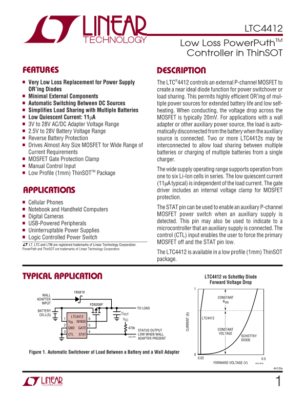
FEATURES DESCRIPTIO Very Low Loss Replacement for Power Supply The LTC®4412 controls an external P-channel MOSFET to OR’ing Diodes create a near ideal diode function for power switchover or Minimal External Components load sharing. This permits highly efficient OR’ing of mul- Automatic Switching Between DC Sources tiple power sources for extended battery life and low self- Simplifies Load Sharing with Multiple Batteries heating. When conducting, the voltage drop across the Low Quiescent Current: 11μA MOSFET is typically 20m V. For applications with a wall 3V to 28V AC/DC Adapter Voltage Range adapter or other auxiliary power source, the load is auto- 2.5V to 28V Battery Voltage Range matically disconnected from the battery when the auxiliary Reverse Battery Protection source is connected. Two or more LTC4412s may be Drives Almost Any Size MOSFET for Wide Range of interconnected to allow load sharing between multiple Current Requirements batteries or charging of multiple batteries from a single MOSFET Gate Protection Clamp charger. Manual Control Input
The wide supply operating range supports operation from
Low Profile (1mm) Thin SOTTM Package
one to six Li-Ion cells in series. The low quiescent current (11μA typical) is independent of the load current. The gate
CU RR EN (A
APPLICATIO S driver includes an internal voltage clamp for MOSFET protection.
Cellular Phones
The STAT pin can be used to enable an auxiliary P-channel
Notebook and Handheld Computers
MOSFET power switch when an auxiliary supply is
Digital Cameras
detected. This pin may also be used to indicate to a
USB-Powered Peripherals
microcontroller that an auxiliary supply is connected. The
Uninterruptable Power Supplies
control (CTL) input enables the user to force the primary
Logic Controlled Power Switch
MOSFET off and the STAT pin low.
, LT, LTC and LTM are registered trademarks of Linear Technology Corporation. Power Path and Thin SOT are trademarks of Linear Technology Corporation.
The LTC4412 is available in a low profile (1mm) Thin SOT package.
TYPICAL APPLICATIO LTC4412 vs Schottky Diode Forward Voltage Drop
CONSTANT
ADAPTER
INPUT
FDN306P
TO LOAD
BATTERY
CELL(S)
LTC4412
LTC4412
VIN SENSE
GND GATE 470k
STATUS OUTPUT CONSTANT LOW WHEN WALL VOLTAGE
CTL STAT
4412 F01 SCHOTTKY
ADAPTER PRESENT
DIODE
Figure 1. Automatic Switchover of Load Between a Battery and a Wall Adapter
FORWARD VOLTAGE (V) 4412 F01b
4412fa
Page Summary Contents For LINEAR TECHNOLOGY LTC4412 User's Manual
Manual Details
| Brand | Linear |
|---|---|
| Pages | 12 |
| File Size | 156.17 KB |
| Published | June 17, 2026 |
Enter the captcha to get the download link:

Frequently Asked Questions
What is the low quiescent current consumption of this controller?
The typical quiescent supply current (I_QFL) is 11μA.
How does the LTC4412 handle multiple power sources?
It enables load sharing between multiple batteries or charging from a single charger, and detects auxiliary AC/DC adapter connections automatically.
What input voltage range can the device support?
The operating supply ranges from 2.5V to 28V, supporting AC/DC adapters and batteries.
Is there protection for the MOSFET?
Yes, the gate driver includes an internal voltage clamp for MOSFET protection.