LINEAR TECHNOLOGY LTC1877 User's Manual
Summary
Maximize power efficiency with the LTC1877 high-efficiency monolithic synchronous step-down regulator. Featuring up to 95% efficiency, ultra-low quiescent current (<1mA), and stable operation across a wide range (2.65V–10V), this core component is perfect for portable and battery-powered electronics. The detailed manual covers advanced features like constant frequency operation, low dropout capability, and burst mode functionality. Ideal for engineers developing cellular phones, personal appliances, and high-performance monitoring equipment requiring reliable power regulation.
Page 1 Text Content
LTC1877 High Efficiency
Monolithic Synchronous Step-Down Regulator FEATURES DESCRIPTIO
High Efficiency: Up to 95% The LTC®1877 is a high efficiency monolithic synchro- Very Low Quiescent Current: Only 10µA nous buck regulator using a constant frequency, current During Operation mode architecture. Supply current during operation is 600m A Output Current at VIN = 5V only 10µA and drops to < 1µA in shutdown. The 2.65V to 2.65V to 10V Input Voltage Range 10V input voltage range makes the LTC1877 ideally suited 550k Hz Constant Frequency Operation for both single and dual Li-Ion battery-powered applica- Synchronizable from 400k Hz to 700k Hz tions. 100% duty cycle provides low dropout operation, Selectable Burst Mode TM Operation or extending battery life in portable systems. Pulse Skipping Mode
Switching frequency is internally set at 550k Hz, allowing
No Schottky Diode Required
the use of small surface mount inductors and capacitors.
Low Dropout Operation: 100% Duty Cycle
For noise sensitive applications the LTC1877 can be
0.8V Reference Allows Low Output Voltages
externally synchronized from 400k Hz to 700k Hz. Burst
Shutdown Mode Draws < 1µA Supply Current
Mode operation is inhibited during synchronization or
±2% Output Voltage Accuracy
EF FI CI EN CY when the SYNC/MODE pin is pulled low, preventing low
Current Mode Control for Excellent Line and
frequency ripple from interfering with audio circuitry.
Load Transient Response Overcurrent and Overtemperature Protected The internal synchronous switch increases efficiency and Available in 8-Lead MSOP Package eliminates the need for an external Schottky diode. Low
output voltages are easily supported with the 0.8V feed-
APPLICATIO
back reference voltage. The LTC1877 is available in a
Cellular Telephones space saving 8-lead MSOP package. Lower input voltage Wireless Modems applications (less than 7V abs max) should refer to the Personal Information Appliances LTC1878 data sheet. Portable Instruments Distributed Power Systems
, LTC and LT are registered trademarks of Linear Technology Corporation. Battery-Powered Equipment Burst Mode is a trademark of Linear Technology Corporation.
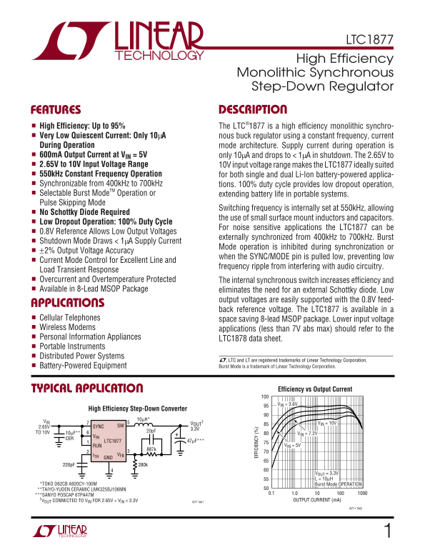
TYPICAL APPLICATIO Efficiency vs Output Current VIN = 3.6V
High Efficiency Step-Down Converter
VOUT VIN = 10V
2.65V SYNC SW
TO 10V 10µF** VIN = 7.2V
LTC1877 47µF***
RUN VIN = 5V
ITH VFB GND
VOUT = 3.3V L = 10µH
*TOKO D62CB A920CY-100M Burst Mode OPERATION **TAIYO-YUDEN CERAMIC LMK325BJ106MN
***SANYO POSCAP 6TPA47M
†VOUT CONNECTED TO VIN FOR 2.65V < VIN < 3.3V OUTPUT CURRENT (m A)
1877 TA01
1877 • TA02
Page Summary Contents For LINEAR TECHNOLOGY LTC1877 User's Manual
Manual Details
| Brand | Linear |
|---|---|
| Pages | 16 |
| File Size | 227.56 KB |
| Published | June 03, 2026 |
Enter the captcha to get the download link:

Frequently Asked Questions
What is the LTC1877's operating current consumption in shutdown mode?
The supply current drops to less than 1mA in shutdown mode, or even lower (10mA) when measured during operation for specific modes.
Can I adjust the switching frequency?
Yes, it can be externally synchronized from 400kHz to 700kHz (internal default is 550kHz).