# A B C D E F G H I J K L M N O P Q R S T U V W X Y Z

LINEAR TECHNOLOGY LTC3780 User's Manual

Summary

The LTC3780 is a high-efficiency, synchronous buck-boost controller designed for robust DC power management in demanding environments. Utilizing advanced single inductor technology, it regulates voltage across extremely wide input and output ranges (4V to 36V). This manual provides comprehensive technical specifications, operational modes (including Burst Mode and Forced Continuous), and detailed application circuits. It is the ideal solution for high-power battery devices, automotive systems, telecom infrastructure, and industrial control requiring superior performance and reliability in power distribution.
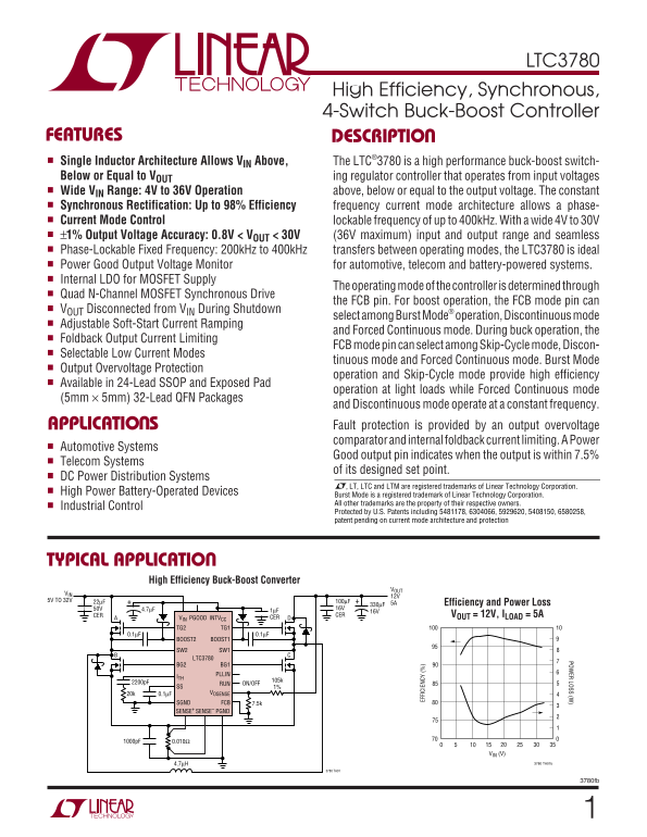
📄 Preview PAGE OF 28

Page 1 Text Content

LTC3780

POW ER LOSS (W

High Efficiency, Synchronous, 4-Switch Buck-Boost Controller

FEATURES DESCRIPTIO Single Inductor Architecture Allows VIN Above, The LTC®3780 is a high performance buck-boost switch- Below or Equal to VOUT ing regulator controller that operates from input voltages Wide VIN Range: 4V to 36V Operation above, below or equal to the output voltage. The constant Synchronous Rectification: Up to 98% Efficiency frequency current mode architecture allows a phase- Current Mode Control lockable frequency of up to 400k Hz. With a wide 4V to 30V ±1% Output Voltage Accuracy: 0.8V < VOUT < 30V (36V maximum) input and output range and seamless Phase-Lockable Fixed Frequency: 200k Hz to 400k Hz transfers between operating modes, the LTC3780 is ideal Power Good Output Voltage Monitor for automotive, telecom and battery-powered systems. Internal LDO for MOSFET Supply

The operating mode of the controller is determined through

Quad N-Channel MOSFET Synchronous Drive

the FCB pin. For boost operation, the FCB mode pin can

VOUT Disconnected from VIN During Shutdown

select among Burst Mode® operation, Discontinuous mode

Adjustable Soft-Start Current Ramping

and Forced Continuous mode. During buck operation, the

Foldback Output Current Limiting

FCB mode pin can select among Skip-Cycle mode, Discon-

Selectable Low Current Modes

tinuous mode and Forced Continuous mode. Burst Mode

Output Overvoltage Protection

operation and Skip-Cycle mode provide high efficiency

Available in 24-Lead SSOP and Exposed Pad

operation at light loads while Forced Continuous mode

(5mm × 5mm) 32-Lead QFN Packages

and Discontinuous mode operate at a constant frequency.

EF FI CI EN CY

APPLICATIO S Fault protection is provided by an output overvoltage comparator and internal foldback current limiting. A Power

Automotive Systems

Good output pin indicates when the output is within 7.5%

Telecom Systems

of its designed set point.

DC Power Distribution Systems

, LT, LTC and LTM are registered trademarks of Linear Technology Corporation.

High Power Battery-Operated Devices Burst Mode is a registered trademark of Linear Technology Corporation.

All other trademarks are the property of their respective owners.

Industrial Control

Protected by U.S. Patents including 5481178, 6304066, 5929620, 5408150, 6580258, patent pending on current mode architecture and protection

TYPICAL APPLICATIO

High Efficiency Buck-Boost Converter

5V TO 32V 22µF 100µF

330µF 5A+ Efficiency and Power Loss

CER CER VOUT = 12V, ILOAD = 5A

VIN PGOOD INTVCC CER

TG2 TG1

BOOST2 BOOST1

SW2 SW1

LTC3780

BG2 BG1 PLLIN

RUN ON/OFF

SS 1%

20k 0.1µF VOSENSE

SGND FCB 7.5k SENSE+ SENSE– PGND

VIN (V)

4.7µH 3780 TA01b

3780 TA01

3780fb

Page Summary Contents For LINEAR TECHNOLOGY LTC3780 User's Manual

Page 1 LTC3780 POW ER LOSS (W High Efficiency, Synchronous, 4-Switch Buck-Boost Controller FEATURES DESCRIPTIO Single Inductor Architecture Allows VIN Above, The LTC®3780 is a high performance buck-boost swi...
Page 2 LTC3780 ABSOLUTE MAXIMUM RATINGS (Note 1) Input Supply Voltage (VIN) –0.3V to 36V Peak Output Current &lt;10µs (TG1, TG2, BG1, BG2) 3A Topside Driver Voltages INTVCC Peak Output Current 40m A (BOOST1,...
Page 3 LTC3780 ELECTRICAL CHARACTERISTICS The ● indicates specifications which apply over the full operating temperature range, otherwise specifications are at TA = 25°C. VIN = 15V unless otherwise noted. SY...
Page 4 LTC3780 ELECTRICAL CHARACTERISTICS The ● indicates specifications which apply over the full operating temperature range, otherwise specifications are at TA = 25°C. VIN = 15V unless otherwise noted. SY...
Page 5 IN TV CC ND XT SW IT CH OL TA GE (V SU PP LY UR RE NT (µ A) EF FI CI EN CY LTC3780 TYPICAL PERFOR A CE CHARACTERISTICS TA = 25°C unless otherwise noted. Efficiency vs Output Current Efficiency vs Outp...
Page 6 LTC3780 TYPICAL PERFOR A CE CHARACTERISTICS TA = 25°C unless otherwise noted. Continuous Current Mode Continuous Current Mode Continuous Current Mode (CCM, VIN = 6V, VOUT = 12V) (CCM, VIN = 12V, VOUT ...
Page 7 (m V) EN SE (m V) FR EQ UE NC (k Hz EN SE LTC3780 TYPICAL PERFOR A CE CHARACTERISTICS TA = 25°C unless otherwise noted. Oscillator Frequency Undervoltage Reset Minimum Current Sense vs Temperature vs ...
Page 8 LTC3780 TYPICAL PERFOR A CE CHARACTERISTICS TA = 25°C unless otherwise noted. Load Step Load Step Load Step VOUT VOUT VOUT 500m V/DIV 500m V/DIV 500m V/DIV IL IL 5A/DIV 5A/DIV 5A/DIV 200µs/DIVVIN = 18...
Page 9 LTC3780 PI FU CTIO S (SSOP/QFN) VOSENSE (Pin 6/Pin 4): Error Amplifier Feedback Input. This BOOST2, BOOST1 (Pins 13, 24/Pins 14, 27): Boosted pin connects the error amplifier input to an external resi...
Page 10 LTC3780 BLOCK DIAGRA INTVCC VIN BOOST2 STBYMD FCB FCB BUCK LOGIC INTVCC RSENSE BOOST INTVCC SW1 LOGIC 1.2V 4(VFB) BOOST1 1.2µA OV SS 0.86V INTVCC SLOPE EA VOSENSE 4(VFB) SENSE+ SENSE– PLLIN PHASE DET ...
Page 11 LTC3780 OPERATIO MAIN CONTROL LOOP SS voltage while CSS is slowly charged during start-up. This “soft-start” clamping prevents abrupt current from The LTC3780 is a current mode controller that provide...
Page 12 LTC3780 OPERATIO and Switch A is turned on for the remainder of the cycle. CLOCK Switches A and B will alternate, behaving like a typical SWITCH A synchronous buck regulator. The duty cycle of switch ...
Page 13 LTC3780 OPERATIO The duty cycle of Switch C decreases until the minimum When the FCB pin voltage is lower than 0.8V, the control- duty cycle of the converter in Boost mode reaches ler behaves as a con...
Page 14 LTC3780 OPERATIO diode of Synchronous Switch B or the Schottky diode, INTVCC/EXTVCC POWER which is in parallel in with Synchronous Switch B, is used Power for all power MOSFET drivers and most interna...
Page 15 LTC3780 OPERATIO OUTPUT OVERVOLTAGE PROTECTION In every Boost mode cycle, current is limited by a voltage reference, which is proportional to the ITH pin voltage. The An overvoltage comparator guards ...
Page 16 LTC3780 OP ER AT IN FR EQ UE NC (k Hz APPLICATIO S I FOR ATIO Figure 11 is a basic LTC3780 application circuit. External Inductor Selection component selection is driven by the load requirement, The o...
Page 17 LTC3780 AX (L OA D) EN SE (m V) APPLICATIO S I FOR ATIO where ∆IL is peak-to-peak inductor ripple current. In Buck input square wave current. Use a low ESR capacitor sized mode, the maximum average lo...
Page 18 LTC3780 OR AL IZ ED N- RE SI ST AN CE (Ω APPLICATIO S I FOR ATIO Power MOSFET Selection and Switch B operates in Buck mode as the synchronous Efficiency Considerations rectifier. Its power dissipation...
Page 19 LTC3780 APPLICATIO S I FOR ATIO Schottky Diode (D1, D2) Selection INTVCC Regulator and Light Load Operation An internal P-channel low dropout regulator produces 6V The Schottky diodes D1 and D2 shown ...
Page 20 LTC3780 APPLICATIO S I FOR ATIO EXTVCC Connection Topside MOSFET Driver Supply (CA, DA, CB, DB) The LTC3780 contains an internal P-channel MOSFET Referring to Figure 11, the external bootstrap capacit...
Page 21 LTC3780 APPLICATIO S I FOR ATIO The Standby Mode (STBYMD) Pin Function Fault Conditions: Overvoltage Protection The Standby mode (STBYMD) pin provides several choices A comparator monitors the output ...
Page 22 LTC3780 APPLICATIO S I FOR ATIO 3. INTVCC current. This is the sum of the MOSFET driver The highest value of ripple current occurs at the maximum and control currents. This loss can be reduced by inpu...
Page 23 LTC3780 APPLICATIO S I FOR ATIO Double-check the TJ in the MOSFET with 70°C ambient CIN is chosen to filter the square current in Buck mode. In temperature: this mode, the maximum input current peak i...
Page 24 LTC3780 APPLICATIO S I FOR ATIO Use immediate vias to connect the components (in- Connect the INTVCC decoupling capacitor CVCC closely cluding the LTC3780’s SGND and PGND pins) to the to the INTVCC an...
Page 25 LTC3780 APPLICATIO S I FOR ATIO VPULLUP COUT CSS PGOOD BOOST1 SS TG1 D2 LTC3780 SENSE+ SW1 SENSE–4 CC1 VIN RC ITH EXTVCC R2 CVCC R1 VOSENSE INTVCC SGND BG1 RSENSE RUN PGND FCB BG2 D1 PLLFLTR SW2 DB EN...
Page 26 LTC3780 PACKAGE DESCRIPTIO G Package 24-Lead Plastic SSOP (5.3mm) (Reference LTC DWG # 05-08-1640) 0.42 ±0.03 0.65 BSC RECOMMENDED SOLDER PAD LAYOUT BSC 0.05 NOTE: (.002) 1. CONTROLLING DIMENSION: MIL...
Page 27 LTC3780 PACKAGE DESCRIPTIO UH Package 32-Lead Plastic QFN (5mm × 5mm) (Reference LTC DWG # 05-08-1693) 3.50 REF (4 SIDES) PACKAGE OUTLINE 0.25 ± 0.05 0.50 BSC RECOMMENDED SOLDER PAD LAYOUT APPLY SOLDE...
Page 28 LTC3780 TYPICAL APPLICATIO VOUT 12V RPU 5A CA COUT 0.22µFVPULLUP D2 6.8n F PGOOD BOOST1 SS TG1 CC2 Si7884DP LTC3780 DA 1N5819HW SENSE+ SW1 CF 0.1µF 3300p F SENSE– VIN 5.6k Si7884DP ITH EXTVCC R1 CVCC ...

Manual Details

Brand Linear
Pages 28
File Size 467.90 KB
Published June 03, 2026
49 views

Enter the captcha to get the download link:

captcha

Frequently Asked Questions

What is the wide operational voltage range of the LTC3780?

The controller supports a wide V range, operating from 4V to 36V for both input and output voltages.

How can I monitor if the power rails are stable during operation?

Use the Power Good (PGOOD) output pin, which indicates when the voltage is within 7.5% of its designed set point.

What forms of protection are available against system faults?

It provides protection via an output overvoltage comparator and internal foldback current limiting feature.

Which operating modes optimize efficiency at low loads?

Selectable low current modes, such as Burst Mode or Discontinuous mode, help maintain high efficiency when operating at light loads.