# A B C D E F G H I J K L M N O P Q R S T U V W X Y Z

LINEAR TECHNOLOGY LTC1474 LTC1475 Data Sheet Manual

Summary

These industry-grade DC/DC converters are designed for sophisticated power management in battery-powered applications. The LTC1474/LTC1475 series delivers high efficiency (over 92%) while maintaining exceptionally low standby current, making it ideal for extending battery life in digital devices. The manual provides comprehensive details on configuring these reliable step-down converters utilizing wide input voltage ranges and incorporating critical protective measures like low-battery detection, perfect for wireless modems, portable instruments, and cellular electronics requiring dependable, optimized power solutions.
📄 Preview PAGE OF 20

Page 1 Text Content

LTC1474/LTC1475

Low Quiescent Current High Efficiency Step-Down

Converters

FEATURES DESCRIPTION

High Efficiency: Over 92% Possible The LTC®1474/LTC1475 series are high efficiency step- Very Low Standby Current: 10µA Typ down converters with internal P-channel MOSFET power Available in Space Saving 8-Lead MSOP Package switches that draw only 10µA typical DC supply current at Internal 1.4Ω Power Switch (VIN = 10V) no load while maintaining output voltage. The LTC1474 Wide VIN Range: 3V to 18V Operation uses logic-controlled shutdown while the LTC1475 fea- Very Low Dropout Operation: 100% Duty Cycle tures pushbutton on/off. Low-Battery Detector Functional During Shutdown

The low supply current coupled with Burst Mode TM opera-

Programmable Current Limit with Optional

tion enables the LTC1474/LTC1475 to maintain high effi-

Current Sense Resistor (10m A to 400m A Typ)

ciency over a wide range of loads. These features, along

Short-Circuit Protection

with their capability of 100% duty cycle for low dropout

Few External Components Required

and wide input supply range, make the LTC1474/LTC1475

Active Low Micropower Shutdown: IQ = 6µA Typ

ideal for moderate current (up to 300m A) battery-powered

Pushbutton On/Off (LTC1475 Only)

applications.

3.3V, 5V and Adjustable Output Versions

The peak switch current is user-programmable with an optional sense resistor (defaults to 325m A minimum if not

APPLICATIONS used) providing a simple means for optimizing the design

EF FI CI EN CY

for lower current applications. The peak current control

Cellular Telephones and Wireless Modems

also provides short-circuit protection and excellent start-

4m A to 20m A Current Loop Step-Down Converter

up behavior. A low-battery detector that remains functional

Portable Instruments

in shutdown is provided .

Battery-Operated Digital Devices Battery Chargers The LTC1474/LTC1475 series availability in 8-lead MSOP Inverting Converters and SO packages and need for few additional components Intrinsic Safety Applications provide for a minimum area solution.

, LTC and LT are registered trademarks of Linear Technology Corporation. Burst Mode is a trademark of Linear Technology Corporation.

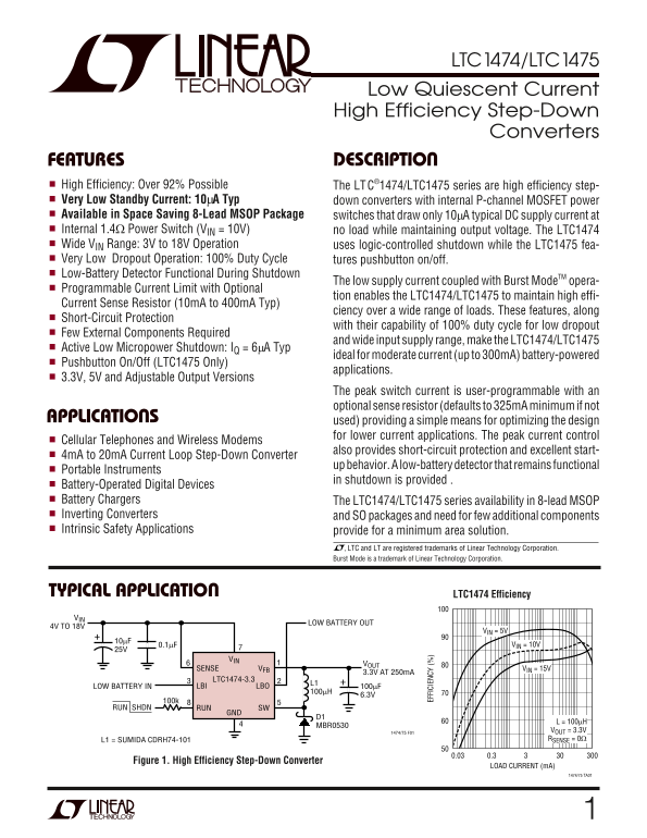
TYPICAL APPLICATION LTC1474 Efficiency VIN

LOW BATTERY OUT

4V TO 18V

VIN = 5V 0.1µF10µF VIN = 10V

SENSE VFB VIN = 15V

3.3V AT 250m A

LTC1474-3.3

LOW BATTERY IN LBI LBO 100µF

RUN SHDN RUN SW

MBR0530

1474/75 F01 VOUT = 3.3V L1 = SUMIDA CDRH74-101 RSENSE = 0Ω

Figure 1. High Efficiency Step-Down Converter

LOAD CURRENT (m A)

1474/75 TA01

Page Summary Contents For LINEAR TECHNOLOGY LTC1474 LTC1475 Data Sheet Manual

Page 1 LTC1474/LTC1475 Low Quiescent Current High Efficiency Step-Down Converters FEATURES DESCRIPTION High Efficiency: Over 92% Possible The LTC®1474/LTC1475 series are high efficiency step- Very Low Standb...
Page 2 LTC1474/LTC1475 ABSOLUTE MAXIMUM RATINGS Input Supply Voltage (VIN) .........................–0.3V to 20V Operating Ambient Temperature Range Switch Current (SW, SENSE) 750m A Commercial 0°C to 70°C S...
Page 3 LTC1474/LTC1475 ELECTRICAL CHARACTERISTICS TA = 25°C, VIN = 10V, VRUN = open, RSENSE = 0, unless otherwise noted. SYMBOL PARAMETER CONDITIONS MIN TYP MAX UNITS VFB Feedback Voltage ILOAD = 50m A 1.205...
Page 4 LE AK AG CU RR EN (µ A) CU RR EN TR IP HR ES HO LD (m A) EF FI CI EN CY LTC1474/LTC1475 TYPICAL PERFORMANCE CHARACTERISTICS Efficiency vs Input Voltage Line Regulation Load Regulation FIGURE 1 CIRCUIT...
Page 5 LTC1474/LTC1475 PIN FUNCTIONS VOUT/VFB (Pin 1): Feedback of Output Voltage. In the fixed SW (Pin 5): Drain of Internal PMOS Power Switch. Cath- versions, an internal resistive divider divides the outp...
Page 6 LTC1474/LTC1475 OPERATIO (Refer to Functional Diagram) The LTC1474/LTC1475 are step-down converters with Peak Inductor Current Programming internal power switches that use Burst Mode operation to The ...
Page 7 LTC1474/LTC1475 APPLICATIONS INFORMATION EN SE (Ω The basic LTC1474/LTC1475 application circuit is shown ments. Lower peak currents have the advantage of lower in Figure 1, a high efficiency step-down...
Page 8 LTC1474/LTC1475 IN DU CT OR AL UE (µ H) APPLICATIONS INFORMATION If the LMIN calculated is not practical, a larger IPEAK should section, increased inductance requires more turns of wire be used. Altho...
Page 9 LTC1474/LTC1475 APPLICATIONS INFORMATION CIN and COUT Selection negligible ESR. AVX and Marcon are good sources for these capacitors. At higher load currents, when the inductor current is continuous, ...
Page 10 LTC1474/LTC1475 APPLICATIONS INFORMATION small that this loss is negligible at loads above a To minimize no-load supply current, resistor values in the milliamp but at no load accounts for nearly all ...
Page 11 LTC1474/LTC1475 APPLICATIONS INFORMATION LTC1475 Pushbutton On/Off and the depressed switch state is detected by the microcon- Microprocessor Interface troller through its input. The microcontroller t...
Page 12 LTC1474/LTC1475 APPLICATIONS INFORMATION with a built-in internal disconnect. The user needs to where P is the power dissipated by the regulator and θJA assess his/her application to determine whether...
Page 13 LTC1474/LTC1475 APPLICATIONS INFORMATION OUTPUT DIVIDER REQUIRED WITH ADJUSTABLE VERSION ONLY LTC1474 VOUT VFB RUN R1 LBO 1000p F RSENSE COUT SENSE GND SW 0.1µF CIN BOLD LINES INDICATE HIGH PATH CURRE...
Page 14 LTC1474/LTC1475 TYPICAL APPLICATIONS VIN 10p F 3.5V TO 18V VIN 1% VOUT SENSE VFB 3V 100m A LBI LTC1474 LBO SUMIDA CDRH73-271 6.3V 3 PARALLEL STANDARD RESISTORS RUN RUN SW PROVIDE LEAST EXPENSIVE SOLUT...
Page 15 LTC1474/LTC1475 TYPICAL APPLICATIONS MBR0530 VOUT –12V 70m A 10p F 22µF†† VIN 25V 3.5V TO 6V 1% VOUT SENSE VFB 12V 70m A LBI LTC1474 LBO 1% 100k RUN RUN SW VIN (V) ILOAD(MAX) COILTRONICS CTX200-4 D1 A...
Page 16 LTC1474/LTC1475 TYPICAL APPLICATIONS 3.5V TO 12V ON/OFF†† TP0610 SENSE VOUT LTC1474-5 L* VIN (V) ILOAD(MAX) LBI LBO RUN SW 10M GND 190m A MBR0530 –5V SUMIDA CDRH74-101 140m A AT VIN = 5V* AVX TPSC106M...
Page 17 LTC1474/LTC1475 TYPICAL APPLICATIONS VIN 4V TO 18V SENSE VOUT 3.3V 250m A LTC1474-3.3 100µF†† LBI LBO 6.3V 1M 100k RUN RUN SW D1 MBR0530 SUMIDA CDRH73-101 AVX TPSC475M035 1474/75 F16 †† AVX TPSC107M00...
Page 18 LTC1474/LTC1475 PACKAGE DESCRIPTION Dimensions in inches (millimeters) unless otherwise noted. MS8 Package 8-Lead Plastic MSOP (LTC DWG # 05-08-1660) 0° – 6° TYP SEATING PLANE 0.021 ± 0.006 0.012 0.00...
Page 19 LTC1474/LTC1475 PACKAGE DESCRIPTION Dimensions in inches (millimeters) unless otherwise noted. S8 Package 8-Lead Plastic Small Outline (Narrow 0.150) (LTC DWG # 05-08-1610) (0.203 – 0.254) 0°– 8° TYP ...
Page 20 LTC1474/LTC1475 TYPICAL APPLICATION VIN 3.5V to 18V 1.8M 1% VOUT 1M SENSE VFB 2.5V 250m A MMBT2N2222LT1 100k 100µF† ON 1% L* LTC1475 LBO 6.3V LBI/OFF SW OFFON MBR0530 SUMIDA CDRH73-101 AVX TPSC475M035...

Manual Details

Brand Linear
Pages 20
File Size 234.73 KB
Published May 25, 2026
146 views

Enter the captcha to get the download link:

captcha

Frequently Asked Questions

What is the basic operational efficiency of the LTC1474/LTC1475?

The series boasts high efficiency, exceeding 92% in performance.

Does this device feature low-power standby detection?

Yes, it includes a built-in low-battery detector that remains functional during shutdown.

What is the maximum specified range for the input voltage (V_IN)?

The unit supports operation across 3V up to 18V, with an absolute max rating of -0.3V to 20V.

Can I use this converter in applications requiring a manual power cycle?

The LTC1475 model is equipped with a dedicated pushbutton on/off switch.