# A B C D E F G H I J K L M N O P Q R S T U V W X Y Z

LINEAR TECHNOLOGY LT3724 User's Manual

Summary

The LT3724 is a high-voltage DC/DC switching regulator controller engineered for robust power management (4V to 60V). This manual details advanced features such as Burst Mode operation, programmable soft-start control, and internal voltage biasing capabilities. It offers reliable solutions for demanding industrial applications, including avionics, telecom power systems, and automotive heavy equipment.
📄 Preview PAGE OF 24

Page 1 Text Content

POW ER LOSS (W

LT3724

High Voltage, Current Mode Switching Regulator Controller

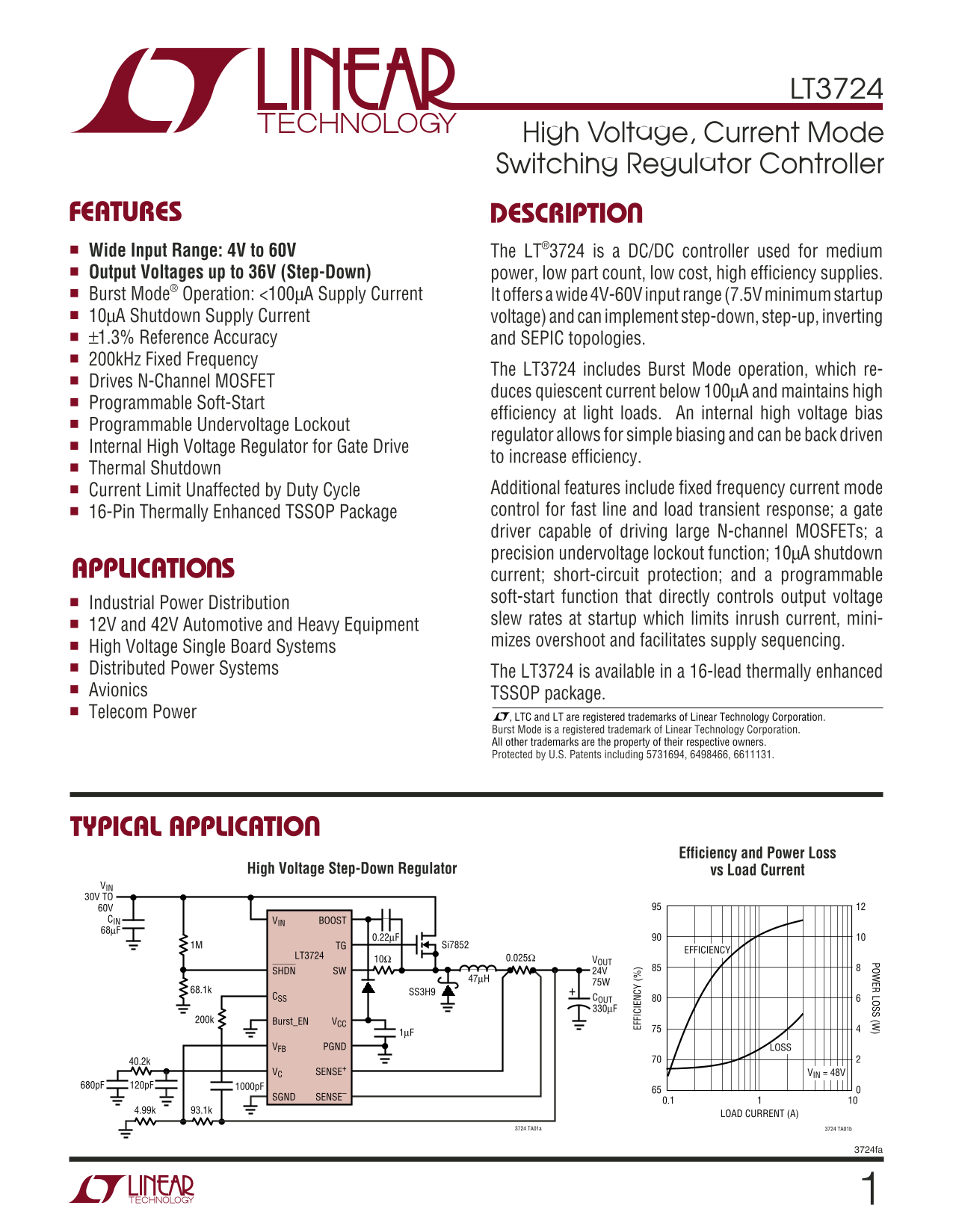
FEATURES DESCRIPTIO Wide Input Range: 4V to 60V The LT®3724 is a DC/DC controller used for medium Output Voltages up to 36V (Step-Down) power, low part count, low cost, high efficiency supplies. Burst Mode® Operation: <100µA Supply Current It offers a wide 4V-60V input range (7.5V minimum startup 10µA Shutdown Supply Current voltage) and can implement step-down, step-up, inverting ±1.3% Reference Accuracy and SEPIC topologies. 200k Hz Fixed Frequency

The LT3724 includes Burst Mode operation, which re-

Drives N-Channel MOSFET

duces quiescent current below 100µA and maintains high

Programmable Soft-Start

efficiency at light loads. An internal high voltage bias

Programmable Undervoltage Lockout

regulator allows for simple biasing and can be back driven

Internal High Voltage Regulator for Gate Drive

to increase efficiency.

Thermal Shutdown

Current Limit Unaffected by Duty Cycle Additional features include fixed frequency current mode 16-Pin Thermally Enhanced TSSOP Package control for fast line and load transient response; a gate driver capable of driving large N-channel MOSFETs; a precision undervoltage lockout function; 10µA shutdown

APPLICATIO S current; short-circuit protection; and a programmable

soft-start function that directly controls output voltage

Industrial Power Distribution

slew rates at startup which limits inrush current, mini-

12V and 42V Automotive and Heavy Equipment

EF FI CI EN CY

mizes overshoot and facilitates supply sequencing.

High Voltage Single Board Systems Distributed Power Systems The LT3724 is available in a 16-lead thermally enhanced Avionics TSSOP package. Telecom Power , LTC and LT are registered trademarks of Linear Technology Corporation.

Burst Mode is a registered trademark of Linear Technology Corporation. All other trademarks are the property of their respective owners. Protected by U.S. Patents including 5731694, 6498466, 6611131.

TYPICAL APPLICATIO

Efficiency and Power Loss vs Load Current High Voltage Step-Down Regulator

VIN 30V TO 60V CIN VIN BOOST 68µF

1M TG Si7852

EFFICIENCY

LT3724 0.025Ω

10Ω VOUT

SHDN SW 24V

68.1k SS3H9

CSS COUT

200k Burst_EN VCC

VFB PGND LOSS

VC SENSE+ VIN = 48V

SGND SENSE–

LOAD CURRENT (A)

3724 TA01a 3724 TA01b

3724fa

Page Summary Contents For LINEAR TECHNOLOGY LT3724 User's Manual

Page 1 POW ER LOSS (W LT3724 High Voltage, Current Mode Switching Regulator Controller FEATURES DESCRIPTIO Wide Input Range: 4V to 60V The LT®3724 is a DC/DC controller used for medium Output Voltages up to ...
Page 2 LT3724 ABSOLUTE AXI RATI GS PACKAGE/ORDER I FOR ATIO (Note 1) TOP VIEW Input Supply Voltage (VIN) 65V to –0.3V VIN BOOST Boosted Supply Voltage (BOOST) 80V to –0.3V NC TG Switch Voltage (SW)(Note 8) 6...
Page 3 LT3724 ELECTRICAL CHARACTERISTICS The ● denotes the specifications which apply over the full operating temperature range, otherwise specifications are at TA = 25°C. VIN = 20V, VCC = BOOST = BURST_EN =...
Page 4 UV LO HR ES HO LD , R IS IN (V (V SH UT DO TH RE SH OL D, IS IN (V LT3724 TYPICAL PERFOR A CE CHARACTERISTICS Shutdown Threshold (Rising) Shutdown Threshold (Falling) vs Temperature vs Temperature VCC...
Page 5 CU RR EN SE NS TH RE SH OL (m V) (S EN SE EN SE ) ( µA LT3724 TYPICAL PERFOR A CE CHARACTERISTICS I(SENSE Operating Frequency Error Amp Reference + SENSE ) vs VSENSE (CM) vs Temperature vs Temperature...
Page 6 LT3724 PI FU CTIO S VIN (Pin 1): The VIN pin is the main supply pin and should optimize transient response. Connecting a 100p F or greater be decoupled to SGND with a low ESR capacitor located high fr...
Page 7 LT3724 PI FU CTIO S SW (Pin 14): In step-down applications the SW pin is MOSFET with a short and wide, typically 0.02” width, PCB connected to the cathode of an external clamping Schottky trace to min...
Page 8 LT3724 FU CTIO AL DIAGRA VIN UVLO (&lt;4V) 8V VCC VIN REGULATOR BOOST VIN UVLO CIN CBOOST INTERNAL REGULATOR SUPPLY RAIL BOOSTED SWITCH DRIVER TG DRIVE CONTROL RA FEEDBACK REFERENCE 1.231V L1 RSENSESW...
Page 9 LT3724 OPERATIO (Refer to Functional Diagram) The LT3724 is a PWM controller with a constant fre- VCC/Boosted Supply quency, current mode control architecture. It is designed An internal VCC regulator...
Page 10 LT3724 OPERATIO (Refer to Functional Diagram) start of the next cycle or until the bootstrapped capacitor switching resumes. An internal clamp on the VC pin is set is fully charged. at 100m V below th...
Page 11 LT3724 OPERATIO (Refer to Functional Diagram) Soft-Start artificial ramp on the sensed current to increase the rising slope as duty cycle increases. The soft-start function controls the slew rate of t...
Page 12 LT3724 APPLICATIO S I FOR ATIO The basic LT3724 step-down (buck) application, shown in compensation circuit is ineffective and current mode the Typical Application on the front page, converts a larger...
Page 13 LT3724 APPLICATIO S I FOR ATIO For maximum efficiency, minimize RDS(ON) and CRSS. Low The internal VCC regulator operating range limits the RDS(ON) minimizes conduction losses while low CRSS maximum t...
Page 14 LT3724 APPLICATIO S I FOR ATIO Step-Down Converter: Input Capacitor Selection Step-Down Converter: Output Capacitor Selection A local input bypass capacitor is required for buck con- The output capaci...
Page 15 LT3724 APPLICATIO S I FOR ATIO L1 VSUPPLY R2 COUT SHDN PIN VFB PIN Figure 2. Output Voltage Feedback Divider Figure 3. Undervoltage Lockout Circuit The VFB pin input bias current is typically 25n A, s...
Page 16 LT3724 APPLICATIO S I FOR ATIO The desired soft-start rise time (t SS) is programmed via a programming capacitor CSS1, using a value that corre- sponds to 2µA average current during the soft-start int...
Page 17 LT3724 APPLICATIO S I FOR ATIO Inductor current typically doesn’t reach IMAX in the few VC cycles that occur before soft-start becomes active, but can with high input voltages or small inductors, so t...
Page 18 LT3724 APPLICATIO S I FOR ATIO 2. I2R losses are calculated from the DC resistances of the input capacitor, and the ground return of the VCC capaci- MOSFET, the inductor, the sense resistor, and the i...
Page 19 LT3724 APPLICATIO S I FOR ATIO RA CBOOST VIN BOOST TG M1 LT3724 L1 RB RSENSE SHDN SW CSS D2 BURST_EN VCC CVCC VOUT VFB PGND VC SENSE+ SGND SENSE– CC1 R1 CC2 Figure 9. LT3724 Layout Diagram (See PCB La...
Page 20 LT3724 TYPICAL APPLICATIO S 12V to 24V/50W Boost (Step-Up) Converter D1 RSENSE BAV99 0.015Ω VIN BOOST 8V TO16V 25V TG 10µH 25V LT3724 VOUT C1 24V AT 50W SHDN SW SBM540 1500p F RCSS POW ER LOSS (W 200k...
Page 21 POW ER LOSS (W LT3724 TYPICAL APPLICATIO S High Voltage LED Driver with Dimmer Control LED L1 VIN 8V TO 60V C1 (OPTIONAL) VIN BOOST 4.7M ZXMN10A07F OPTIONAL LT3724 DIMMER SHDN SW CONTROL CVCC 1k Hz BU...
Page 22 LT3724 TYPICAL APPLICATIO S 12V Step-Down with VCC Back Driven from VOUT and Ceramic Capacitor in Output Filter VIN 15V TO 60V C6 CIN 0.1µF 499k VIN BOOST R3 R7 49.9k 20Ω SHDN TG Si7852DP RCSS LT3724 ...
Page 23 LT3724 PACKAGE DESCRIPTIO FE Package 16-Lead Plastic TSSOP (4.4mm) (Reference LTC DWG # 05-08-1663) Exposed Pad Variation BC SEE NOTE 4 2.94 (.252) (.116) 0.45 ±0.05 BSC 0.65 BSC 2RECOMMENDED SOLDER P...
Page 24 LT3724 TYPICAL APPLICATIO S Inverting –12V 1.5A Converter VIN 18V TO 36V VIN BOOST LT3724 TG M1 SHDN SW 50V CSS D2D1BD1A CSS RCSS 88.7k 16V VOUT VFB PGND –12V R2 SENSE+ CC2 CC1 RSENSE COUT1 GND SENSE–...

Manual Details

Brand Linear
Pages 24
File Size 276.26 KB
Published June 22, 2026
1 views

Enter the captcha to get the download link:

captcha

Frequently Asked Questions

What is the acceptable input voltage range for this controller?

The LT3724 accepts a wide input voltage range from 4V to 60V.

Does it offer different topographies for power conversion?

Yes, it can implement step-down, step-up, inverting, and SEPIC topologies.

What is the minimum standby current when using Burst Mode?

The continuous supply current in Burst Mode is induced below 100µA.

What features ensure stable operation during voltage fluctuations?

It includes a programmable soft-start function to limit overshoots and reduce inrush current at startup.