LINEAR TECHNOLOGY LT3572 Data Sheet User Manual
Summary
This advanced power management IC provides highly integrated dual full-bridge driving capability for piezoelectric motors, featuring a robust 900mA boost converter. It efficiently drives two independent piezo actuators up to 40V from moderate input voltages (2.7V–10V). The accompanying manual details all electrical characteristics, synchronization options, soft-start functionality, and operating parameters required to integrate this specialized component into high-performance motor control systems.
Page 1 Text Content
LT3572
Dual Full-Bridge Piezo Driver with 900m A Boost Converter
FEATURES DESCRIPTION ■ 2.7V to 10V Input Voltage Range
The LT®3572 is a highly integrated dual Piezo motor driver
■ 900m A Boost Converter
capable of driving two Piezo motors at up to 40V from a
■ Dual Full-Bridge Piezo Drivers
5V supply. Each Piezo driver can be independently turned
■ Programmable Switching Frequency from
on or off along with the boost converter.
500k Hz to 2.25MHz
The boost regulator has a soft-start capability that limits the
■ Synchronizable Up to 2.5MHz
inrush current at start-up. The boost regulator switching
■ Soft-Start
frequency is set by an external resistor or the frequency can
■ Separate Enable for Each Piezo Driver and Boost
be synchronized by an external clock. A PGOOD pin indicates
Converter
when the output of the boost converter is in regulation and
■ Available in a 4mm × 4mm 20-Pin QFN Package
the Piezo drivers are allowed to start switching. The LT3572 is available in a (4mm × 4mm) 20-pin QFN
APPLICATIONS
package.
■ Piezo Motor Drive , LT, LTC and LTM are registered trademarks of Linear Technology Corporation.
All other trademarks are the property of their respective owners.
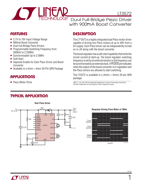
TYPICAL APPLICATION
Dual Piezo Driver
10μH VOUT
VIN Response Driving Piezo Motor at 70k Hz
3V TO 5V
VIN SW VOUT 15p F 576k
SHDN 10μF
100k SHDNA FB
VOUTA
SHDNB
24.3k 20V/DIV
PWMA OUTA
PWMB LT3572
VOUTA
4.7μF SYNC OUTA
3572 TA01a 20V/DIV
PGOOD
RT OUTB
PWMA 2V/DIV
SS OUTB42.2k
10n F 3572 TA01b
2μs/DIV
3572fa
Page Summary Contents For LINEAR TECHNOLOGY LT3572 Data Sheet User Manual
Manual Details
| Brand | Linear |
|---|---|
| Pages | 12 |
| File Size | 163.01 KB |
| Published | June 17, 2026 |
Enter the captcha to get the download link:

Frequently Asked Questions
What input voltage range does the LT3572 support?
It operates within an input voltage range of 2.7V to 10V.
How can the drivers be synchronized across multiple motors?
The Piezo drivers are synchronizable up to 2.5MHz using an external clock.
What is the specific frequency range for the programmable switching frequency?
The programmable switching frequency ranges from a minimum of 500kHz up to 2.25MHz.
Are there special mounting considerations for the QFN package?
Yes, Pin 21 must be soldered to ground on the PCB using the exposed pad.