# A B C D E F G H I J K L M N O P Q R S T U V W X Y Z

LINEAR TECHNOLOGY LT1339 User's Manual

Summary

This professional controller IC is engineered for high-power synchronous DC/DC conversion up to 60V. It provides robust control over dual N-channel MOSFETs, featuring advanced protection such as programmable average current limiting, undervoltage lockout, and soft start sequencing. Designed for complex power systems, the device offers precise, stable outputs needed in data center, telecommunications, industrial, and automotive applications requiring high efficiency and reliable operation across wide input variations.
📄 Preview PAGE OF 20

Page 1 Text Content

LT1339

High Power Synchronous DC/DC Controller FEATURES DESCRIPTION

High Voltage: Operation Up to 60V The LT®1339 is a high power synchronous current mode High Current: Dual N-Channel Synchronous Drive switching regulator controller. The IC drives dual

Handles Up to 10,000p F Gate Capacitance N-channel MOSFETs to create a single IC solution for high Programmable Average Load Current Limiting power DC/DC converters in applications up to 60V.

5V Reference Output with 10m A External

The LT1339 incorporates programmable average current

Loading Capability

limiting, allowing accurate limiting of DC load current

Programmable Fixed Frequency Synchronizable

independent of inductor ripple current. The IC also incor-

Current Mode Operation Up to 150k Hz

porates user-adjustable slope compensation for minimi-

Undervoltage Lockout with Hysteresis

zation of magnetics at duty cycles up to 90%.

Programmable Start Inhibit for Power Supply

Sequencing and Protection The LT1339 timing oscillator operating frequency is pro- Adaptive Nonoverlapping Gate Drive Prevents grammable and can be synchronized up to 150k Hz. Mini- Shoot-Through mum off-time operation provides main switch protection. The IC also incorporates a soft start feature that is gated by both shutdown and undervoltage lockout conditions.

APPLICATIONS

An output phase reversal pin allows flexibility in configu-

48V Telecom Power Supplies

ration of converter types, including inverting and negative

Personal Computers and Peripherals

topologies.

Distributed Power Converters Industrial Control Systems

EF FI CI EN CY

Lead-Acid Battery Backup Systems

Automotive and Heavy Equipment , LTC and LT are registered trademarks of Linear Technology Corporation.

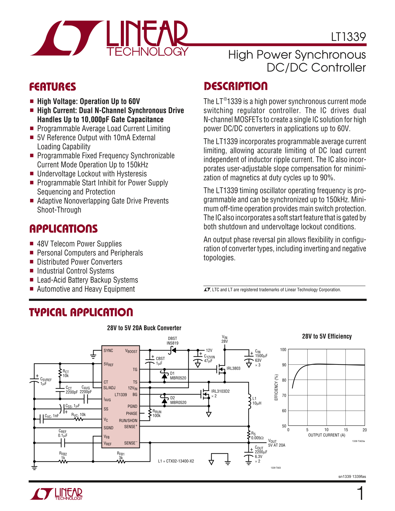
TYPICAL APPLICATION

28V to 5V 20A Buck Converter

VIN 28V to 5V Efficiency

IN5819

SYNC VBOOST 12V CIN +C12VIN

+CBST 1500µF

5VREF 1µF

TG IRL3803

C5VREF MBR0520

CT TS

CCT CAVG SL/ADJ 12VIN

2200p F 2200p F IRL3103D2

LT1339 BG

IAVG D2 L1 MBR0520 10µH

CSS, 1µF PGND

RVC, 10k PHASE

CVC, 1n F 100k

VC RUN/SHDN

SGND SENSE+

0.1µF OUTPUT CURRENT (A)

VOUT 1339 TA03a

VREF SENSE–

5V AT 20A COUT RFB2 RFB1 2200µF 1k 3k 6.3V

L1 = CTX02-13400-X2 × 2

1339 TA03

sn1339 1339fas

Page Summary Contents For LINEAR TECHNOLOGY LT1339 User's Manual

Page 1 LT1339 High Power Synchronous DC/DC Controller FEATURES DESCRIPTION High Voltage: Operation Up to 60V The LT®1339 is a high power synchronous current mode High Current: Dual N-Channel Synchronous Driv...
Page 2 LT1339 XI ARBSOLUTE TI PACKAGE/ORDER FOR ATIO (Note 1) ORDER PART Supply Voltages TOP VIEW NUMBER Power Supply Voltage (12VIN) ...............–0.3V to 20V SYNC VBOOST Topside Supply Voltage (VBOOST) 5...
Page 3 LT1339 ELECTRICAL CHARA TERISTICS 12VIN = VBOOST = 12V, VC = 2V, TS = 0V, VFB = VREF = 1.25V, CTG = CBG = 3000p F, TA = 25°C unless otherwise noted. SYMBOL PARAMETER CONDITIONS MIN TYP MAX UNITS Error...
Page 4 ER RO AM PL IF IE VO LT AG GA IN (k V/ V) 2V IN HU TD OW CU RR EN (µ A) BO OS SU PP LY UR RE NT (m A) LT1339 TYPICAL PERFORMANCE CHARACTERISTICS Boost Supply Current vs 12VIN Supply Current vs 5V Refe...
Page 5 BO TT OM AT TR AN SI TI ON IM ES (n s) SO FT TA RT HA RG CU RR EN (µ A) LT1339 TYPICAL PERFORMANCE CHARACTERISTICS SU PP LY UR RE NT (m Soft Start Charge Current RUN/SHDN Rising Threshold RUN/SHDN Thr...
Page 6 2V IN (V LT1339 TYPICAL PERFORMANCE CHARACTERISTICS AX IM UM UT CY CL RU N/ SH DN IN PU CU RR EN (n Sense Amplifier Input Bias Sense Amplifier Input Bias Current (Source) vs Temperature Current (Sink)...
Page 7 LT1339 PIN FUNCTIONS SYNC (Pin 1): Oscillator Synchronization Pin with TTL- VREF (Pin 10): Bandgap Generated Voltage Reference Level Compatible Input. Input drives internal rising edge Decoupling. Con...
Page 8 LT1339 FU CTIO AL BLOCK DIAGRA VIN VBOOST PHASE CT 5VREF 12VIN MAIN SWITCH TG NONOVERLAPPING SWITCH LOGIC SYNC SWITCH UVLO CIRCUIT SL/ADJ ONE SHOT SENSE+ SYNC RSENSE × 15 SENSE– VOUT IC1 CURRENT SENSE...
Page 9 LT1339 OPERATION (Refer to Functional Block Diagram) The current comparator trip threshold is set on the VC pin, output gate drive signals, insuring that the switch gate which is the output of a trans...
Page 10 LT1339 APPLICATIONS INFORMATION RSENSE Selection for Output Current the minimum off-time of the PWM controller. This limits maximum duty cycle (DCMAX) to: RSENSE generates a voltage that is proportion...
Page 11 LT1339 APPLICATIONS INFORMATION impedance of the IAVG pin. The integrator corner fre- sourcing capabilities of that supply, causing the system to quency is typically set 1 to 2 orders of magnitude bel...
Page 12 LT1339 APPLICATIONS INFORMATION the converter input supply is enabled with no voltage on Oscillator Synchronization the LT1339 12VIN pin, the LT1339 driver output clamps The LT1339 oscillator generate...
Page 13 LT1339 APPLICATIONS INFORMATION Subharmonic oscillations can be eliminated by augment- internal current limit functions are affected such that the ing the increasing ripple current slope (S1) in the c...
Page 14 LT1339 APPLICATIONS INFORMATION further increasing the effective compensation slope up to 5VREF RSL1 20% for a given setting. LT1339 45k SL/ADJ4 Design Example: RSL2 1339 • F07a VIN = 20V 30k VOUT = 1...
Page 15 LT1339 APPLICATIONS INFORMATION In high voltage applications (VIN > 20V), the topside switch 2000 hours (three months) lifetime; it is advisable to is required to slew very large voltages. As VIN i...
Page 16 LT1339 APPLICATIONS INFORMATION is also small. However, since the FET gate must switch up This type of prebias circuit is used in the 48V to 5V, 50A past the 48V input voltage, transition loss can bec...
Page 17 LT1339 TYPICAL APPLICATIONS to .8 2- Tr an si st or yn ch ro no us or ar Co nv er te Q1 D1 TD N0 6H UR S1 T1 UT C5 D2 U2 , L TC -2 1, 8V UR S1 IN C1 p F 0µ U1 GN D1 OU T1 6. 3V 9Ω LT :2 X8 1% IN C2 5....
Page 18 to Is ol at ed yn ch ro no us or ar DC /D Co nv er te LT1339 +V IN SE HV 4. 8µ 0. 1µ IR F1 0N PA NA SO NI ET QP F4 R8 +V OU TYPICAL APPLICATIONS BD 4L T1 +V OU C3 C4 C5 OU TP UT 0Ω FM T7 T1 BA T5 OU C...
Page 19 LT1339 TYPICAL APPLICATIONS 5V to 28V DC/DC Synchronous Boost Converter Limits Input Current at 60A (DC) VOUT 28V 12V COUT 2200µF C12VIN 35V MBR0530 SYNC VBOOST +CBST FMMT619 5VREF IRF3205 RCT Q2 10k ...
Page 20 LT1339 TYPICAL APPLICATION 48V to 5V 50A DC/DC Converter with Input Supply Start-Up Protection 12V 50m A VIN C12VIN IN5819 LT1339 CIN Q1 1500µF SYNC VBOOST +CBST IRFZ44 RCT × 2 5VREF TG Q2 CT MMSZ4684...

Manual Details

Brand Linear
Pages 20
File Size 288.33 KB
Published June 22, 2026
1 views

Enter the captcha to get the download link:

captcha

Frequently Asked Questions

What are the operating voltage limits for the LT1339?

The unit supports high voltage operation up to 60V and handles inputs from -0.3V to 60V.

Does the LT1339 offer current limiting features?

Yes, it incorporates programmable average load current limiting capability for accurate DC load current regulation.

What functions are available for improving power supply reliability?

It includes Undervoltage Lockout (UVLO) with Hysteresis and a Soft Start feature gated by UVLO conditions.

What kind of applications is the LT1339 suitable for?

Applications include Telecom Power Supplies, Personal Computers, Industrial Control Systems, and Automotive/Heavy Equipment usage.