# A B C D E F G H I J K L M N O P Q R S T U V W X Y Z

LINEAR TECHNOLOGY LT1307 Data Sheet - LT1307B Technical Manual

Summary

These micropower DC/DC converters are engineered for extreme low-power applications requiring reliable performance from a single-cell supply, operating efficiently down to 1V. The manual provides comprehensive technical specifications, full efficiency curves, and detailed application circuits. Ideal for developers building portable electronics, battery backup systems, medical instrumentation, and cordless communication devices that demand high energy conservation and minimal component footprint using small ceramic capacitors.
📄 Preview PAGE OF 20

Page 1 Text Content

LT1307/LT1307B

Single Cell Micropower

600k Hz PWM DC/DC Converters

FEATURES DESCRIPTIO Uses Small Ceramic Capacitors The LT®1307/LT1307B are micropower, fixed frequency 50µA Quiescent Current (LT1307) DC/DC converters that operate from an input voltage as 1m A Quiescent Current (LT1307B) low as 1V. First in the industry to achieve true current Operates with VIN as Low as 1V mode PWM performance from a single cell supply, the 600k Hz Fixed Frequency Operation LT1307 features automatic shifting to power saving Burst

Starts into Full Load Mode operation at light loads. High efficiency is main- Low Shutdown Current: 3µA tained over a broad 100µA to 100m A load range. The Low-Battery Detector LT1307B does not shift into Burst Mode operation at light 3.3V at 75m A from a Single Cell loads, eliminating low frequency output ripple at the Automatic Burst Mode® Operation at expense of light load efficiency. The devices contain a low- Light Load (LT1307) battery detector with a 200m V reference and shut down to Continuous Switching at Light Load (LT1307B) less than 5µA. No load quiescent current of the LT1307 is Low VCESAT Switch: 295m V at 500m A 50µA and the internal NPN power switch handles a 500m A current with a voltage drop of just 295m V. Unlike competitive devices, large electrolytic capacitors

APPLICATIO S

are not required with the LT1307/LT1307B in single cell

Pagers applications. The high frequency (600k Hz) switching al-

EF FI CI EN CY

Cordless Telephones lows the use of tiny surface mount multilayer ceramic GPS Receivers (MLC) capacitors along with small surface mount induc- Battery Backup tors. The devices work with just 10µF of output capaci- Portable Electronic Equipment tance and require only 1µF of input bypassing. Glucose Meters

The LT1307/LT1307B are available in 8-lead MSOP, PDIP

Diagnostic Medical Instrumentation

and SO packages. , LTC and LT are registered trademarks of Linear Technology Corporation. Burst Mode is a registered trademark of Linear Technology Corporation.

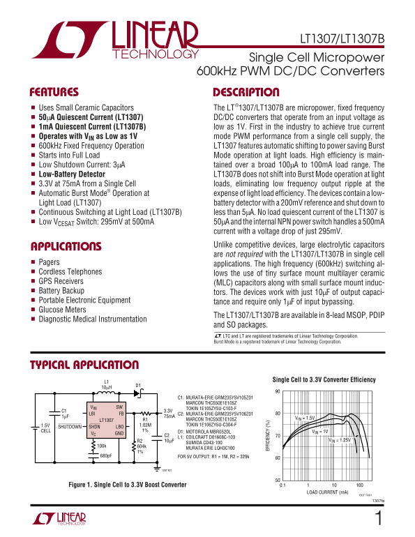
TYPICAL APPLICATIO

Single Cell to 3.3V Converter Efficiency

C1: MURATA-ERIE GRM235Y5V105Z01 MARCON THCS50E1E105Z

VIN SW TOKIN 1E105ZY5U-C103-F

LBI FB C2: MURATA-ERIE GRM235Y5V106Z01

MARCON THCS50E1E105Z VIN = 1.5V

LT1307 R1

1.5V 1.02M TOKIN 1E106ZY5U-C304-F

SHDNSHUTDOWN LBO

CELL 1% D1: MOTOROLA MBR0520L VIN = 1V

VC GND

C2 L1: COILCRAFT D01608C-103

R2 10µF VIN = 1.25V

SUMIDA CD43-100

MURATA ERIE LQH3C100

680p F FOR 5V OUTPUT: R1 = 1M, R2 = 329k

Figure 1. Single Cell to 3.3V Boost Converter 0.1

LOAD CURRENT (m A)

1307 TA01

1307fa

Page Summary Contents For LINEAR TECHNOLOGY LT1307 Data Sheet - LT1307B Technical Manual

Page 1 LT1307/LT1307B Single Cell Micropower 600k Hz PWM DC/DC Converters FEATURES DESCRIPTIO Uses Small Ceramic Capacitors The LT®1307/LT1307B are micropower, fixed frequency 50µA Quiescent Current (LT1307)...
Page 2 LT1307/LT1307B (Note 1)ABSOLUTE AXI U RATI GS VIN, SHDN, LBO Voltage 12V Junction Temperature 125°C SW Voltage 30V Operating Temperature Range FB Voltage VIN + 1V Commercial (Note 2) –20°C to 70°C VC ...
Page 3 LT1307/LT1307B ELECTRICAL CHARACTERISTICS The ● denotes the specifications which apply over the full operating temperature range, otherwise specifications are at TA = 25°C. Commercial Grade 0°C to 70°...
Page 4 LT1307/LT1307B ELECTRICAL CHARA TERISTICS The ● denotes the specifications which apply over the full operating temperature range, otherwise specifications are at TA = 25°C. Industrial Grade –40°C to 8...
Page 5 QU IE SC EN CU RR EN (µ A) QU IE SC EN CU RR EN (µ A) EF FI CI EN CY LT1307/LT1307B TYPICAL PERFOR A CE CHARACTERISTICS 5V Output Efficiency, Circuit of 3.3V Output Efficiency, Circuit of 5V Output Ef...
Page 6 FE ED BA CK OL TA GE (V LT1307/LT1307B TYPICAL PERFOR A CE CHARACTERISTICS Feedback Voltage vs Oscillator Frequency vs Temperature LBI Reference vs Temperature Input Voltage RE FE RE NC VO LT AG (m V)...
Page 7 LT1307/LT1307B PI FU CTIO S VC (Pin 1): Compensation Pin for Error Amplifier. Con- SW (Pin 5): Switch Pin. Connect inductor/diode here. nect a series RC from this pin to ground. Typical values Minimiz...
Page 8 LT1307/LT1307B APPLICATIO S I FOR ATIO OPERATION 200m V. There is no hysteresis in A4, allowing it to be used as an amplifier in some applications. The entire device is The LT1307 combines a current m...
Page 9 LT1307/LT1307B APPLICATIO S I FOR ATIO Trace B. Similarly, Figure 4 details the two circuits with a quite evident, as is this particular device’s 575k Hz switch- load step from 5m A to 45m A with a 1....
Page 10 LT1307/LT1307B OU TP UT OL TA GE OI SE (d Bm S) OU TP UT OI SE OL TA GE (d Bm S) APPLICATIO S I FOR ATIO away from 455k Hz. Figure 8 shows the noise spectrum of To eliminate the low frequency noise of...
Page 11 LT1307/LT1307B APPLICATIO S I FOR ATIO VOUT 200m V/DIV 200m V/DIV AC COUPLED AC COUPLED 51m A 51m A 1m AIL 1m AIL 5ms/DIV 1307 F11a 5ms/DIV 1307 F11b Figure 11a. VC Pin Left Unconnected. Output Ripple...
Page 12 LT1307/LT1307B APPLICATIO S I FOR ATIO LAYOUT HINTS COMPONENT SELECTION The LT1307 switches current at high speed, mandating Inductors careful attention to layout for proper performance. You will not ...
Page 13 LT1307/LT1307B APPLICATIO S I FOR ATIO tions where small size is not critical, Panasonic HFQ series VIN aluminum electrolytic capacitors have been found to per- form well. R2 SHUTDOWN CURRENT Table 2....
Page 14 LT1307/LT1307B APPLICATIO S I FOR ATIO REVERSE BATTERY CONSIDERATIONS tion after sustaining polarity reversal for the life of a single AA alkaline cell. The LT1307 is built on a junction-isolated bipo...
Page 15 LT1307/LT1307B TYPICAL APPLICATIO S Externally Controlled Burst Mode Operation MBR0520 CERAMIC 300k VIN SW VC FB LT1307B CELLS LBO LBI 3.3V GNDSHDN C2* 3.0V IN LOW-POWER C1 Burst Mode OPERATION 49.9k ...
Page 16 LT1307/LT1307B TYPICAL APPLICATIO S Low Cost 2-Cell to 5V VIN L1 1.4V TO 3.3V 10µH C1* C2 220µF VIN SW 220µF 6.3V 6.3V LT1307 1M SHDN FB 0.1µF GND 100k 1307 TA02 C1, C2: PANASONIC ECA0JFQ221 (DIGI-KEY...
Page 17 LT1307/LT1307B TYPICAL APPLICATIO S Single Cell Powered Constant Current LED Driver 10µH D1VIN VIN SW LBO FB NC LT1307B VC LBI 1µF SHDN GND CERAMIC CERAMIC 1307 TA05 ON/OFF L1: MURATA-ERIE LQH3C100K04...
Page 18 LT1307/LT1307B TYPICAL APPLICATIO S Single Cell CCFL Power Supply C1 CCFL 1.5V Q1 Q2 0.1µF VIN SW CERAMIC LT1307B 10k CELL SHDN FB 1N4148 GND VC 1k 10k DIMMING 1307 TA08 1 = OPERATE C1: WIMA MKP-20 0 ...
Page 19 LT1307/LT1307B PACKAGE DESCRIPTION N8 Package 8-Lead PDIP (Narrow .300 Inch) (Reference LTC DWG # 05-08-1510) 0.400* (10.160) MAX 0.065 (1.651) 0.009 – 0.015 TYP +0.035 MIN (0.508) 0.325 –0.015 MIN0.0...
Page 20 LT1307/LT1307B TYPICAL APPLICATIO LCD Bias Generator –VOUT VOUT 16V TO 24V 5m A FROM 1 CELL VIN SW 15m A FROM 2 CELLS 35m A FROM 3 CELLS LT1307 10p F 3.3M 1, 2 OR 3 VC FB C1 CELLS 100k GNDSHDN 1307 TA...

Manual Details

Brand Linear
Pages 20
File Size 369.55 KB
Published May 25, 2026
167 views

Enter the captcha to get the download link:

captcha

Frequently Asked Questions

What is the low input voltage requirement for operation?

The LT1307/LT1307B can operate with an input voltage (VIN) as low as 1V.

What is the maximum operating temperature range for industrial use?

The Industrial grade devices can operate from -40°C to 85°C.