LINEAR TECHNOLOGY LT1259 LT1260 User's Manual
Summary
Achieve reliable high-speed signal integrity with the LT1259/LT1260 current feedback amplifiers. Designed for demanding portable and video applications, these low-power dual/triple channels feature up to 130MHz bandwidth and optimized shutdown features for maximum efficiency. This comprehensive datasheet provides detailed electrical characteristics, package options, and robust integration guidance, making it essential reading for engineers developing specialized multiplexing or high-speed cable driver solutions.
Page 1 Text Content
LT1259/LT1260
Low Cost Dual and Triple 130MHz Current Feedback Amplifiers with Shutdown
FEATURES DESCRIPTIO 90MHz Bandwidth on ±5V
The LT®1259 contains two independent 130MHz current
0.1d B Gain Flatness >30MHz
feedback amplifiers, each with a shutdown pin. These
Completely Off in Shutdown, 0µA Supply Current
amplifiers are designed for excellent linearity while driving
High Slew Rate: 1600V/µs
cables and other low impedance loads. The LT1260 is a
Wide Supply Range: ±2V(4V) to ±15V(30V)
triple version especially suited to RGB video applications.
60m A Output Current
These amplifiers operate on all supplies from single 5V to
Low Supply Current: 5m A/Amplifier
±15V and draw only 5m A per amplifier when active.
Differential Gain: 0.016%
When shut down, the LT1259/LT1260 amplifiers draw
Differential Phase: 0.075°
zero supply current and their outputs become high
Fast Turn-On Time: 100ns
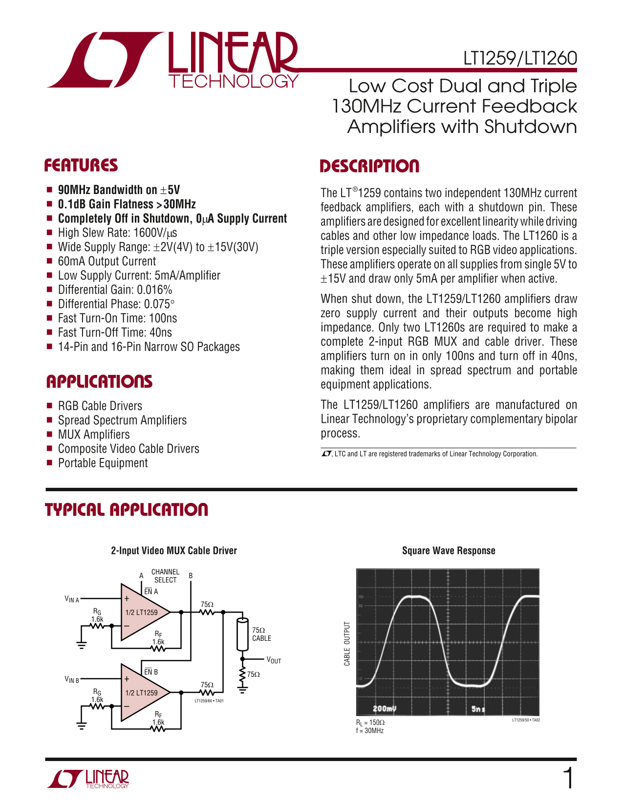
impedance. Only two LT1260s are required to make a
Fast Turn-Off Time: 40ns
complete 2-input RGB MUX and cable driver. These
14-Pin and 16-Pin Narrow SO Packages CA BL UT PU
amplifiers turn on in only 100ns and turn off in 40ns, making them ideal in spread spectrum and portable
APPLICATIO S equipment applications.
RGB Cable Drivers The LT1259/LT1260 amplifiers are manufactured on Spread Spectrum Amplifiers Linear Technology’s proprietary complementary bipolar MUX Amplifiers process.
Composite Video Cable Drivers
, LTC and LT are registered trademarks of Linear Technology Corporation.
Portable Equipment
TYPICAL APPLICATIO
Square Wave Response2-Input Video MUX Cable Driver
BCHANNEL
SELECT EN A
VIN A
1/2 LT1259RG
CABLE
VIN B
1/2 LT1259RG
1.6k LT1259/60 • TA01
LT1259/50 • TA02
1.6k RL = 150Ω
f = 30MHz
Page Summary Contents For LINEAR TECHNOLOGY LT1259 LT1260 User's Manual
Manual Details
| Brand | Linear |
|---|---|
| Pages | 12 |
| File Size | 324.08 KB |
| Published | June 22, 2026 |
Enter the captcha to get the download link:

Frequently Asked Questions
What is the operational frequency range for these amplifiers?
They operate at 130MHz with a 90MHz bandwidth.
Does the amplifier design suit video applications, and what benefits does it offer?
Yes, they are optimized for RGB cable drivers and features a proprietary complementary bipolar process ideal for spread spectrum equipment.
What is the typical power consumption when the device is shut down?
When using the shutdown pin, the LT1259/LT1260 draws 0mA supply current.
How fast are these amplifiers at turning on and off?
The amplifiers can turn on in only 100ns and turn off in 40ns.
What is the usable temperature range for these components?
The operating temperature range is specified as -40°C to 85°C.