LINEAR LT1510 LT1510-5 Data Sheet
Summary
The LT1510/LT1510-5 is a high-efficiency Constant-Voltage/Constant-Current battery charger IC ideal for fast and reliable charging of NiCd, NiMH, and Lithium-Ion batteries. This manual provides comprehensive technical documentation, detailing operational specifications, package options, and advanced application circuits. It is designed for power electronics engineers and developers needing minimal component solutions to create precise, safe, and highly efficient battery charging management systems.
Page 1 Text Content
查询DS8供应商
LT1510/LT1510-5 Constant-Voltage/
Constant-Current Battery Charger
FEATURES
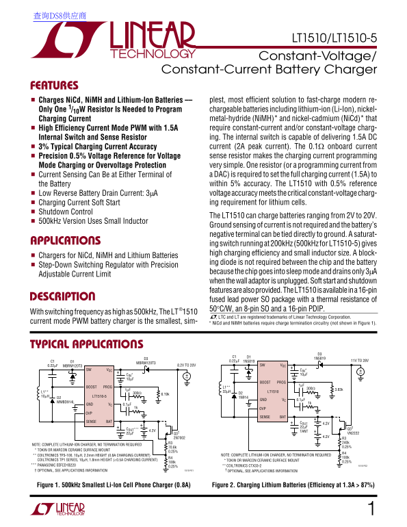
Charges Ni Cd, Ni MH and Lithium-Ion Batteries –– plest, most efficient solution to fast-charge modern re- Only One 1/10W Resistor Is Needed to Program chargeable batteries including lithium-ion (Li-Ion), nickel- Charging Current metal-hydride (Ni MH)* and nickel-cadmium (Ni Cd)* that High Efficiency Current Mode PWM with 1.5A require constant-current and/or constant-voltage charg- Internal Switch and Sense Resistor ing. The internal switch is capable of delivering 1.5A DC 3% Typical Charging Current Accuracy current (2A peak current). The 0.1Ω onboard current Precision 0.5% Voltage Reference for Voltage sense resistor makes the charging current programming Mode Charging or Overvoltage Protection very simple. One resistor (or a programming current from Current Sensing Can Be at Either Terminal of a DAC) is required to set the full charging current (1.5A) to the Battery within 5% accuracy. The LT1510 with 0.5% reference Low Reverse Battery Drain Current: 3µA voltage accuracy meets the critical constant-voltage charg- Charging Current Soft Start ing requirement for lithium cells.
Shutdown Control
The LT1510 can charge batteries ranging from 2V to 20V.
500k Hz Version Uses Small Inductor
Ground sensing of current is not required and the battery’s negative terminal can be tied directly to ground. A saturat-
APPLICATIONS ing switch running at 200k Hz (500k Hz for LT1510-5) gives
high charging efficiency and small inductor size. A block-
Chargers for Ni Cd, Ni MH and Lithium Batteries
ing diode is not required between the chip and the battery
Step-Down Switching Regulator with Precision
because the chip goes into sleep mode and drains only 3µA
Adjustable Current Limit
when the wall adaptor is unplugged. Soft start and shutdown features are also provided. The LT1510 is available in a 16-pin
DESCRIPTION fused lead power SO package with a thermal resistance of
®1510 50°C/W, an 8-pin SO and a 16-pin PDIP.
With switching frequency as high as 500k Hz, The LT
, LTC and LT are registered trademarks of Linear Technology Corporation.
current mode PWM battery charger is the smallest, sim- * Ni Cd and Ni MH batteries require charge termination circuitry (not shown in Figure 1).
TYPICAL APPLICATIONS
C1 D1 0.22µF 1N5819 11V TO 28V
MBRM120T3
0.22µF MBRM120T3 8.2V TO 20V SW VCC
SW VCC CIN* +–
CIN* +– 10µF
BOOST PROG
BOOST PROG L1**
L1** 33µH LT1510
10µH LT1510-5 1N914
GND VC 0.1µF
MMBD914L 1k
GND VC 0.1µF
1k OVP
SENSE BAT
SENSE BAT COUT
COUT*** Q3†
4.2V TANT
22µF Q3† VN2222
NOTE: COMPLETE LITHIUM-ION CHARGER, NO TERMINATION REQUIRED
TOKIN OR MARCON CERAMIC SURFACE MOUNT
COILTRONICS TP3-100, 10µH, 2.2mm HEIGHT (0.8A CHARGING CURRENT) NOTE: COMPLETE LITHIUM-ION CHARGER, NO TERMINATION REQUIRED
COILTRONICS TP1 SERIES, 10µH, 1.8mm HEIGHT (<0.5A CHARGING CURRENT) TOKIN OR MARCON CERAMIC SURFACE MOUNT
PANASONIC EEFCD1B220 0.25% COILTRONICS CTX33-2 1510 F02
OPTIONAL, SEE APPLICATIONS INFORMATION 1510 F01 OPTIONAL, SEE APPLICATIONS INFORMATION
Figure 1. 500k Hz Smallest Li-Ion Cell Phone Charger (0.8A) Figure 2. Charging Lithium Batteries (Efficiency at 1.3A > 87%)
Page Summary Contents For LINEAR LT1510 LT1510-5 Data Sheet
Manual Details
| Brand | Linear |
|---|---|
| Pages | 16 |
| File Size | 264.77 KB |
| Published | June 17, 2026 |
Enter the captcha to get the download link:

Frequently Asked Questions
Does charging lithium batteries require termination circuitry?
No, the LT1510 is a complete lithium-ion charger and no termination circuitry is required.
What total voltage range can this charger accommodate?
The device can charge batteries ranging from 2V up to 20V.
How precise can the charging current be set?
Charging current programming has a precision of 0.5% accuracy.
How does the unit behave when the wall adaptor is unplugged?
The chip goes into sleep mode and drains only a low reverse battery drain current of 3μA.