LINEAR LT1494 Data Sheet User Manual LT1495 LT1496
Summary
Discover the LT1494/LT1495/LT1496 ultra-low power operational amplifiers for demanding electronics applications. These high-precision, rail-to-rail op amps feature extremely low supply currents (1.5mA max), ideal for battery- or solar-powered and remote sensing systems. The manual provides comprehensive details covering electrical characteristics, wide operating temperature ranges (-40°C to 125°C), and diverse applications. Essential for engineers designing reliable, high-efficiency instrumentation requiring minimal power draw without sacrificing performance.
Page 1 Text Content
查询LT1494供应商
LT1494/LT1495/LT1496 1.5µA Max, Single, Dual
and Quad Over-The-Top Precision Rail-to-Rail Input and Output Op Amps
FEATURES DESCRIPTIO
Low Supply Current: 1.5µA Max The LT®1494/LT1495/LT1496 are the lowest power Rail-to-Rail Input and Output (IS ≤ 1.5µA) op amps with precision specifications. The Low Offset Voltage: 375µV Max extremely low supply current is combined with excellent Operating Temperature Range: –40°C to 125°C amplifier specifications: input offset voltage is 375µV Over-The-Top TM Inputs Operate Above V+ maximum with a typical drift of only 0.4µV/°C, input offset current is 100p A maximum. A minimum open-loop gain
Wide Supply Range: 2.2V to 36V
(AVOL) of 100V/m V ensures that gain errors are small. The
Single Supply Input Range: –0.3V to 36V
device characteristics change little over the supply range
Low Input Bias Current: 250p A
of 2.2V to ±15V. Supply rejection is 90d B and the common
Low Input Offset Current: 20p A
mode rejection ratio is 90d B. Operation is specified for 3V,
High AVOL: 100V/m V Minimum Driving 100kΩ Load
5V and ±15V supplies. Reverse battery protection
Output Sources and Sinks 500µA Load Current
(–18V␣ min) and inputs that operate above the positive
Reverse Battery Protected to 18V
supply make the LT1494/LT1495/LT1496 easy to use in harsh environments.
UN IT
APPLICATIO S The low bias currents and offset current of the amplifier
permit the use of megohm level source resistors without
Battery- or Solar-Powered Systems
introducing significant errors. Voltage noise at 4µVP-P is
Portable Instrumentation
remarkably low considering the low supply current.
Remote Sensor Amplifier
The LT1494 is available in the 8-Pin MSOP, PDIP and SO
Micropower Filter
packages.The LT1495 is available in plastic 8-Pin PDIP and SO packages with the standard dual op amp pinout.
, LTC and LT are registered trademarks of Linear Technology Corporation. Over-The-Top is a trademark of Linear Technology Corporation. The LT1496 is available in 14-Pin SO and PDIP packages.
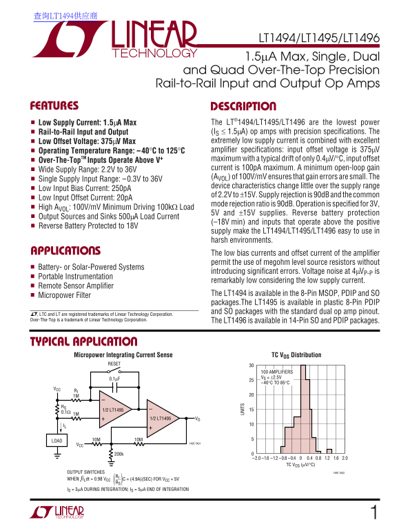
TYPICAL APPLICATION Micropower Integrating Current Sense TC VOS Distribution
RESET
100 AMPLIFIERS VS = ±2.5V
–40°C TO 85°C
RI 1M
1/2 LT1495
1/2 LT1495 VO
LOAD 10M10M
1495 TA01
–1.2 –0.8 –0.4 0.4 0.8 1.2 1.6 2.0–1.6–2.0 TC VOS (µV/°C)
OUTPUT SWITCHES 1495 TA02
WHEN ILdt = 0.98 VCC C = (4.9A)(SEC) FOR VCC = 5VRI
IS = 3µA DURING INTEGRATION; IS = 5µA END OF INTEGRATION
Page Summary Contents For LINEAR LT1494 Data Sheet User Manual LT1495 LT1496
Manual Details
| Brand | Linear |
|---|---|
| Pages | 16 |
| File Size | 248.13 KB |
| Published | June 01, 2026 |
Enter the captcha to get the download link:

Frequently Asked Questions
What is the operating temperature range?
The general operating temperature range is -40°C to 125°C for some versions, or specified by the package (e.g., LT1494C/LT1495C/LT1496C for -40°C to 85°C).
Are these amplifiers suitable for battery-powered systems?
Yes, their low bias and offset currents allow use in Battery- or Solar-Powered Systems without significant errors.
What is the maximum supply voltage range?
The high side operation supports a single supply input range of -0.3V to 36V, and operates up to 36V.