LINEAR dn435f Data Sheet & Manual
Summary
Minimize component count with this advanced single IC DC/DC converter solution. Designed to simplify the creation of complex power systems, it supports multiple topologies (Boost, SEPIC, Cuk) and provides dual error amplification for both positive or negative outputs. The manual details features like soft-start, anti-inrush current control, high efficiency, and adjustable switching frequency. Essential for embedded engineers building highly reliable electronic subsystems requiring maximum versatility in a small footprint.
Page 1 Text Content
Single Resistor Sets Positive or Negative Output for DC/DC Converter – Design Note 435 Jesus Rosales Introduction the use of tiny component sizes, reducing the real estate
Many electronic subsystems, such as VFD (vacuum required and the output ripple. If power loss is a concern, fl ourecent display), TFT-LCD, GPS or DSL applications, switching at a lower frequency reduces switching losses, require more than just a simple step-down or step-up improving effi ciency. The switching frequency can be set DC/DC converter. They may require inverting, noninverting from 200k Hz to 2.5MHz via a single resistor from the RT converters or both. Designers usually resort to different pin to ground. The device can also be synchronized to an regulator ICs to control various polarity outputs, thus external clock via the SYNC pin.
increasing the inventory list. The LT®3580 solves this
Soft-Start and Undervoltage Lockout
problem by controlling either positive or negative outputs
To alleviate high inrush current levels during start-up, the
using the same feedback confi guration. It contains an in-
LT3580 includes a soft-start feature which controls the
tegrated 2A, 42V switch and packs many popular features
ramp rate of the switch current by the use of a capacitor
such as soft-start, adjustable frequency, synchronization
from SS to ground.
and a wide input range into a small footprint. The LT3580 comes in an 8-pin 3mm × 3mm DFN or MSOP packages The SHDN pin in the LT3580 serves two purposes. Tying and can be used in multiple confi gurations such as boost, it high or low turns the converter on or off. In situations SEPIC, fl yback and Cuk topologies. where the input supply is current limited, has a high source
impedance or ramps up/down slowly, the SHDN pin can
Sensing Output Voltage Has Never Been Easier
be confi gured to provide undervoltage lockout through
The LT3580 has a novel FB pin architecture that simpli-
a simple resistor divider from VIN to ground.
fi es the design of inverting and noninverting topologies.
Namely, there are two internal error amplifi ers; one senses Boost Converters
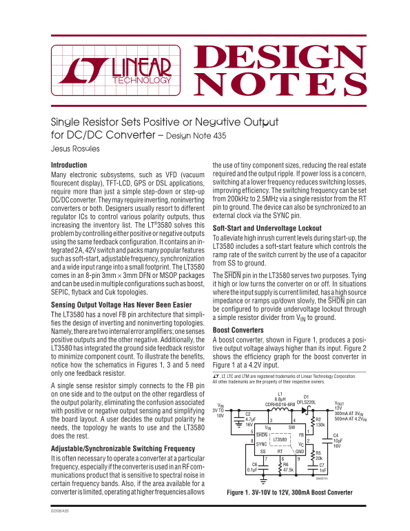
positive outputs and the other negative. Additionally, the A boost converter, shown in Figure 1, produces a posi- LT3580 has integrated the ground side feedback resistor tive output voltage always higher than its input. Figure 2 to minimize component count. To illustrate the benefi ts, shows the effi ciency graph for the boost converter in notice how the schematics in Figures 1, 3 and 5 need Figure 1 at a 4.2V input. only one feedback resistor.
L, LT, LTC and LTM are registered trademarks of Linear Technology Corporation. All other trademarks are the property of their respective owners.
A single sense resistor simply connects to the FB pin
on one side and to the output on the other regardless of L1
the output polarity, eliminating the confusion associated DFLS220L VOUT
VIN CDRH5D16-6R8
with positive or negative output sensing and simplifying 3V TO
C2 300m A AT 3VIN
the board layout. A user decides the output polarity he 4.7μF R2 500m A AT 4.2VIN
needs, the topology he wants to use and the LT3580 VIN SW
FBSHDN C4
does the rest.
LT3580 10μF
SYNC VC
Adjustable/Synchronizable Switching Frequency
SS RT GND
R5 It is often necessary to operate a converter at a particular 20k
frequency, especially if the converter is used in an RF com-
munications product that is sensitive to spectral noise in
DN435 F01
certain frequency bands. Also, if the area available for a converter is limited, operating at higher frequencies allows Figure 1. 3V-10V to 12V, 300m A Boost Converter
Page Summary Contents For LINEAR dn435f Data Sheet & Manual
Manual Details
| Brand | Linear |
|---|---|
| Pages | 2 |
| File Size | 88.20 KB |
| Published | May 30, 2026 |
Enter the captcha to get the download link:

Frequently Asked Questions
How does the LT3580 simplify feedback design?
It uses a novel FB pin architecture and integrated ground side feedback resistor, allowing for one sense resistor regardless of output polarity.
Can I use this converter for both positive and negative outputs?
Yes, the device features two internal error amplifiers: one senses positive outputs and the other handles negative ones.
What functions does the SHDN pin serve?
The SHDN pin can either high or low turn the converter on or off, or be configured for undervoltage lockout.