Intel Intersil X93255 Specifications
Summary
This advanced dual solid-state potentiometer (XDCP) offers independent, digitally controlled resistance variable outputs for applications requiring precision adjustments, such as LCD contrast control. Featuring nonvolatile memory and temperature compensation, the device ensures retained settings even after power loss and operates using low-power CMOS technology. This manual provides comprehensive technical specifications, operational guidelines, electrical ratings, and pinout details, making it an essential resource for engineers designing reliable electronic circuits that require durable, adjustable resistance control.
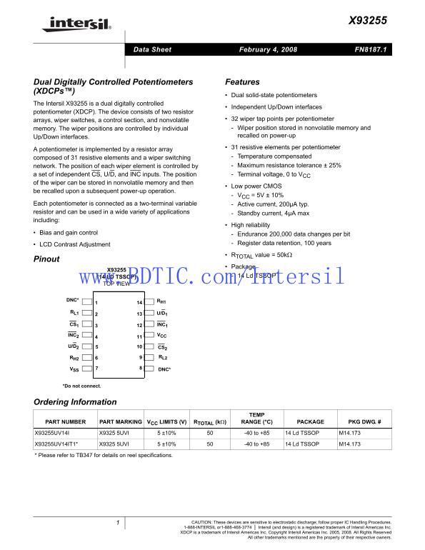
Page 1 Text Content
February 4, 2008 FN8187.1Data Sheet
Dual Digitally Controlled Potentiometers Features (XDCPs™)
Dual solid-state potentiometers
The Intersil X93255 is a dual digitally controlled
Independent Up/Down interfaces
potentiometer (XDCP). The device consists of two resistor
arrays, wiper switches, a control section, and nonvolatile 32 wiper tap points per potentiometer memory. The wiper positions are controlled by individual Wiper position stored in nonvolatile memory and Up/Down interfaces. recalled on power-up 31 resistive elements per potentiometer
A potentiometer is implemented by a resistor array
composed of 31 resistive elements and a wiper switching Temperature compensated network. The position of each wiper element is controlled by Maximum resistance tolerance ± 25%
a set of independent CS, U/D, and INC inputs. The position Terminal voltage, 0 to VCC of the wiper can be stored in nonvolatile memory and then
Low power CMOS
be recalled upon a subsequent power-up operation.
VCC = 5V ± 10%
Each potentiometer is connected as a two-terminal variable Active current, 200µA typ. resistor and can be used in a wide variety of applications Standby current, 4µA max including:
High reliability
Bias and gain control Endurance 200,000 data changes per bit
LCD Contrast Adjustment Register data retention, 100 years RTOTAL value = 50kΩ
Pinout
Package
(14 LD TSSOP) 14 Ld TSSOP
www.BDTIC.com/Intersil TOP VIEW DNC* RH1 RL1 U/D1 CS1 INC1
INC2 VCC
U/D2 CS2
RH2 RL2
VSS DNC*
*Do not connect.
Ordering Information
PART NUMBER PART MARKING VCC LIMITS (V) RTOTAL (kΩ) RANGE (°C) PACKAGE PKG DWG. #
X93255UV14I X9325 5UVI 5 ±10% -40 to +85 14 Ld TSSOP M14.173
X93255UV14IT1* X9325 5UVI 5 ±10% -40 to +85 14 Ld TSSOP M14.173
* Please refer to TB347 for details on reel specifications.
CAUTION: These devices are sensitive to electrostatic discharge; follow proper IC Handling Procedures. 1-888-INTERSIL or1-888-468-3774 Intersil (and design) is a registered trademark of Intersil Americas Inc. XDCP is a trademark of Intersil Americas Inc. Copyright Intersil Americas Inc. 2005, 2008. All Rights Reserved
All other trademarks mentioned are the property of their respective owners.
Page Summary Contents For Intel Intersil X93255 Specifications
Manual Details
| Brand | Intel |
|---|---|
| Pages | 7 |
| File Size | 144.69 KB |
| Published | May 30, 2026 |
Enter the captcha to get the download link:

Frequently Asked Questions
How does the device retain its wiper position when power is lost?
The wiper position is stored in nonvolatile memory and will be recalled upon subsequent power-up operation.
What is the recommended operational temperature range for this potentiometer?
The recommended operating temperature range, under specified conditions, is -40°C to +85°C.
What must I ensure regarding the supply voltage during multiple write operations?
When performing multiple write operations, V must not decrease by more than 150mV from its initial value.
Does this device require special handling precautions due to sensitivity?
Yes, these devices are sensitive to electrostatic discharge and proper IC Handling Procedures must be followed.