Intel Intersil ISL83202 Data Sheet
Summary
This specialized medium-frequency H-Bridge FET driver (ISL83202) independently controls four N-Channel FETs for high-power full bridge applications. The manual details robust features necessary for professional system design, including programmable dead-time control, integrated shoot-through and undervoltage protection, and compatibility with 5V–15V logic levels. Ideal for engineers designing complex power systems such as PWM motor controllers, UPS units, DC Motor Drives, and high-efficiency switching power amplifiers operating up to 200kHz.
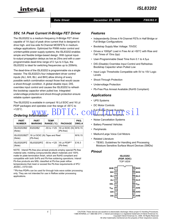
Page 1 Text Content
ISL83202
December 20, 2006Data Sheet FN6382.0
55V, 1A Peak Current H-Bridge FET Driver Features The ISL83202 is a medium-frequency H-Bridge FET driver Independently Drives 4 N-Channel FETs in Half Bridge or capable of 1A (typ) of peak drive current that is designed to Full Bridge Configurations drive high- and low-side N-Channel MOSFETs in medium-
Bootstrap Supply Max Voltage: 70VDC
voltage applications. Optimized for PWM motor control and
uninterruptible power supply systems, the ISL83202 enables Drives a 1000p F Load in Free Air at +50°C with Rise and Fall Times of 15ns (typ)
simple and flexible bridge-based design. With typical input- to-output propagation delays as low as 25ns and with a user- User-Programmable Dead Time from 0.1 to 4.5μs programmable dead-time range of 0.1µs to 4.5µs, the
DIS (Disable) Overrides Input Control and Refreshes
ISL83202 is ideal for switching frequencies up to 200k Hz.
Bootstrap Capacitor when Pulled Low
The dead-time of the ISL83202 is programmable via a single
Input Logic Thresholds Compatible with 5V to 15V Logic
resistor. The ISL83202's four independent driver control
Levels
inputs (ALI, AHI, BLI, and BHI) allow driving of every
Shoot-Through Protection
possible switch combination except those that would cause a shoot-through condition. A global disable input, DIS, Undervoltage Protection overrides input control and causes the ISL83202 to refresh
Pb-Free Plus Anneal Available (Ro HS Compliant)
the bootstrap capacitor when pulled low. Integrated undervoltage protection and shoot-through protection ensure
Applications
reliable system operation.
UPS Systems
The ISL83202 is available in compact 16 Ld SOIC and 16 Ld
PDIP packages and operates over the range of -55°C to DC Motor Controls
Full Bridge Power Supplies
www.BDTIC.com/Inte Switching Power Amplifiers sil Ordering Information
Noise Cancellation Systems
PART PART TEMP. PKG. NUMBER MARKING RANGE (°C) PACKAGE DWG. #
Battery Powered Vehicles
ISL83202IBZ 83202IBZ -55 to +125 16 Ld SOIC (N) M16.15
Peripherals
(Note) (Pb-free)
Medium/Large Voice Coil Motors
ISL83202IBZT 16 Ld SOIC (N) Tape and Reel M16.15 (Note) (Pb-free)
Related Literature ISL83202IPZ ISL83202IPZ -55 to +125 16 Ld PDIP** E16.3 TB363, Guidelines for Handling and Processing
(Note) (Pb-free) Moisture Sensitive Surface Mount Devices (SMDs)
NOTE: Intersil Pb-free plus anneal products employ special Pb-free
Pinout
material sets; molding compounds/die attach materials and 100% matte tin plate termination finish, which are Ro HS compliant and ISL83202 compatible with both Sn Pb and Pb-free soldering operations. Intersil (PDIP, SOIC) Pb-free products are MSL classified at Pb-free peak reflow TOP VIEW temperatures that meet or exceed the Pb-free requirements of IPC/ JEDEC J STD-020.
BHB BHO
**Pb-free PDIPs can be used for through hole wave solder processing
BHI BHS
only. They are not intended for use in Reflow solder processing
applications. BLI BLO
ALI ALO
DEL VDD
VSS AHS
AHI AHO
DIS AHB
CAUTION: These devices are sensitive to electrostatic discharge; follow proper IC Handling Procedures. 1-888-INTERSIL or 1-888-468-3774 Intersil (and design) is a registered trademark of Intersil Americas Inc.
Copyright Intersil Americas Inc. 2006. All Rights Reserved
All other trademarks mentioned are the property of their respective owners.
Page Summary Contents For Intel Intersil ISL83202 Data Sheet
Manual Details
| Brand | Intel |
|---|---|
| Pages | 12 |
| File Size | 202.51 KB |
| Published | May 29, 2026 |
Enter the captcha to get the download link:

Frequently Asked Questions
What is the primary function of the ISL83202?
It is a medium-frequency H-Bridge FET driver designed to drive high- and low-side N-Channel MOSFETs in both Half and Full Bridge configurations.
How can I program the dead time?
The programmable dead-time range is between 0.1μs and 4.5μs, adjustable via a single resistor.
Does this driver offer protection features?
It includes Shoot-Through Protection, Undervoltage Protection, and a global Disable (DIS) input for reliable system operation.
What is the operating temperature range and package type availability?
It operates over -55°C to +125°C and is available in 16 Ld SOIC or 16 Ld PDIP packages.