# A B C D E F G H I J K L M N O P Q R S T U V W X Y Z

Intel INTERSIL ISL6252, ISL6252A Data Sheet

Summary

The ISL6252A is a highly integrated battery charger controller designed for reliable power management in Li-Ion/Li-Poly portable devices like notebooks and PDAs. This manual provides detailed specifications for this synchronous buck topology IC, highlighting advanced features such as high efficiency, programmable input current limits, and precise charge voltage accuracy across extreme temperatures. Essential for electrical engineers, it ensures optimal battery charging while providing robust protection against overvoltage and adapter misuse.
📄 Preview PAGE OF 24

Page 1 Text Content

ISL6252, ISL6252A

July 19, 2007 FN6498.1Data Sheet

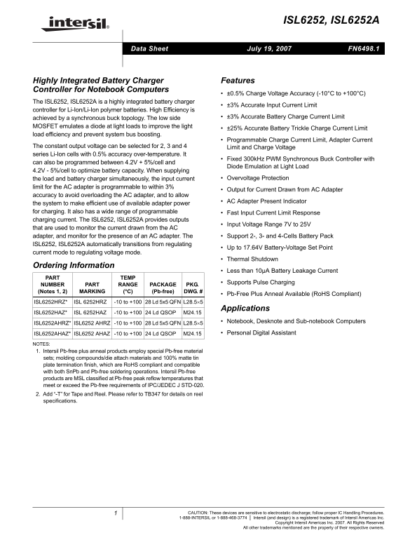
Highly Integrated Battery Charger Features Controller for Notebook Computers

±0.5% Charge Voltage Accuracy (-10°C to +100°C)

The ISL6252, ISL6252A is a highly integrated battery charger

±3% Accurate Input Current Limit

controller for Li-Ion/Li-Ion polymer batteries. High Efficiency is

achieved by a synchronous buck topology. The low side ±3% Accurate Battery Charge Current Limit

MOSFET emulates a diode at light loads to improve the light

±25% Accurate Battery Trickle Charge Current Limit

load efficiency and prevent system bus boosting.

Programmable Charge Current Limit, Adapter Current

The constant output voltage can be selected for 2, 3 and 4 Limit and Charge Voltage series Li-Ion cells with 0.5% accuracy over-temperature. It

Fixed 300k Hz PWM Synchronous Buck Controller with

can also be programmed between 4.2V + 5%/cell and

Diode Emulation at Light Load

4.2V - 5%/cell to optimize battery capacity. When supplying

the load and battery charger simultaneously, the input current Overvoltage Protection

limit for the AC adapter is programmable to within 3%

Output for Current Drawn from AC Adapter

accuracy to avoid overloading the AC adapter, and to allow

AC Adapter Present Indicator

the system to make efficient use of available adapter power for charging. It also has a wide range of programmable Fast Input Current Limit Response charging current. The ISL6252, ISL6252A provides outputs

Input Voltage Range 7V to 25V

that are used to monitor the current drawn from the AC adapter, and monitor for the presence of an AC adapter. The Support 2-, 3- and 4-Cells Battery Pack ISL6252, ISL6252A automatically transitions from regulating

Up to 17.64V Battery-Voltage Set Point

current mode to regulating voltage mode.

Thermal Shutdown

Ordering Information

Less than 10µA Battery Leakage Current

PART TEMP

Supports Pulse Charging

NUMBER PART RANGE PACKAGE PKG. (Notes 1, 2) MARKING (°C) (Pb-free) DWG. #

Pb-Free Plus Anneal Available (Ro HS Compliant)

ISL6252HRZ* ISL 6252HRZ -10 to +100 28 Ld 5x5 QFN L28.5×5

Applications

ISL6252HAZ* ISL 6252HAZ -10 to +100 24 Ld QSOP M24.15

Notebook, Desknote and Sub-notebook Computers

ISL6252AHRZ* ISL6252 AHRZ -10 to +100 28 Ld 5x5 QFN L28.5×5

ISL6252AHAZ* ISL6252 AHAZ -10 to +100 24 Ld QSOP M24.15 Personal Digital Assistant

NOTES: 1. Intersil Pb-free plus anneal products employ special Pb-free material sets; molding compounds/die attach materials and 100% matte tin plate termination finish, which are Ro HS compliant and compatible with both Sn Pb and Pb-free soldering operations. Intersil Pb-free products are MSL classified at Pb-free peak reflow temperatures that meet or exceed the Pb-free requirements of IPC/JEDEC J STD-020. 2. Add “-T” for Tape and Reel. Please refer to TB347 for details on reel specifications.

CAUTION: These devices are sensitive to electrostatic discharge; follow proper IC Handling Procedures.

1-888-INTERSIL or 1-888-468-3774 Intersil (and design) is a registered trademark of Intersil Americas Inc.

Copyright Intersil Americas Inc. 2007. All Rights Reserved

All other trademarks mentioned are the property of their respective owners.

Page Summary Contents For Intel INTERSIL ISL6252, ISL6252A Data Sheet

Page 1 ISL6252, ISL6252A July 19, 2007 FN6498.1Data Sheet Highly Integrated Battery Charger Features Controller for Notebook Computers ±0.5% Charge Voltage Accuracy (-10°C to +100°C) The ISL6252, ISL6252A is...
Page 2 ISL6252, ISL6252A Pinouts ISL6252, ISL6252A ISL6252, ISL6252A (28 LD QFN) (24 LD QSOP) TOP VIEW TOP VIEW LI 24VDD DCIN 1 VA SE ACPRN ACSET EN CSON VD EN CSOP CELLS CSOP PG IN ICOMP CSIN CELLS CSIN LG ...
Page 3 ISL6252, ISL6252A ICM CSIP CSIN ACSET X19.9 CA1 ACPRN VREF DCIN 152kΩ gm3ADAPTER VDD REGULATOR ACLIM CURRENT LIMIT SET MIN CURRENT ICOMP BUFFER BOOT 300k Hz RAMP UGATE MIN PWM VOLTAGE PHASE BUFFER VCO...
Page 4 ISL6252, ISL6252A AC ADAPTER 130k 0.1µF CSON DCIN DCIN R21 2.2Ω 1% CSIP ACSET ACSET ISL6252 ISL6252A IS6252 ISL SYSTEM LOAD VD VDDP VD VDD VDDP TO HOST ACPRN ACPRN UGATE CONTROLLER C4 PHASE ICOMP ICOM...
Page 5 ISL6252, ISL6252A ADAPTER 0.1µF 130k CSON R9 DCIN R21 2.2Ω CSIP CSIP 1% ACSET ACSET SYSTEM LOAD ISL6252 CSIN CSIN ISL6252 ISL6 ISL6252A R22 22Ω µF ISL6252 ISL VD VDDP R10 VDDP C1:10µF 4.7 BOOT OT VCC ...
Page 6 ISL6252, ISL6252A Absolute Maximum Ratings Thermal Information ACSET to GND (Note 3) . . . . . . . . . . . . . . . . . . -0.3V to VDD +0.3V Thermal Resistance θJA (°C/W) θJC (°C/W) DCIN, CSIP, CSON to...
Page 7 ISL6252, ISL6252A Electrical Specifications DCIN CSIP CSIN 18V, CSOP CSON 12V, ACSET 1.5V, ACLIM VREF, VADJ Floating, EN VDD 5V, BOOT-PHASE 5.0V, GND PGND 0V, CVDD 1µF, IVDD 0m A, TA -10°C to +100°C, ...
Page 8 ISL6252, ISL6252A Electrical Specifications DCIN CSIP CSIN 18V, CSOP CSON 12V, ACSET 1.5V, ACLIM VREF, VADJ Floating, EN VDD 5V, BOOT-PHASE 5.0V, GND PGND 0V, CVDD 1µF, IVDD 0m A, TA -10°C to +100°C, ...
Page 9 ISL6252, ISL6252A VD EG LA TI Typical Operating Performance DCIN 20V, 4S2P Li-Battery, TA +25°C, Unless Otherwise Noted. LOAD CURRENT (m A) LOAD CURRENT (μA) FIGURE 4. VDD LOAD REGULATION FIGURE 5. VR...
Page 10 ISL6252, ISL6252A Typical Operating Performance DCIN 20V, 4S2P Li-Battery, TA +25°C, Unless Otherwise Noted. (Continued) INDUCTOR 5V/div CURRENT 2A/div EN BATT BATTERY BATTERY 5V/div INSE INSERTION RE...
Page 11 ISL6252, ISL6252A Typical Operating Performance DCIN 20V, 4S2P Li-Battery, TA +25°C, Unless Otherwise Noted. (Continued) CHARGE CURRENT 1A/div CHLIM 1V/div FIGURE 16. TRICKLE TO FULL-SCALE CHARGING Fu...
Page 12 ISL6252, ISL6252A VADJ charging current and charging voltage. Figure 2 shows the ISL6252 typical application circuit with charging current and VADJ adjusts battery regulation voltage. VADJ VREF for ch...
Page 13 ISL6252, ISL6252A 10% adjustment range (from 4.2V-5% to 4.2V+5%) on values can be set by connecting a resistor divider from CSON regulation voltage. An overall voltage accuracy of VREF or 3.3V to grou...
Page 14 ISL6252, ISL6252A voltage divided by the minimum sense resistor. This can be where Rbot_ACLIM and Rtop_ACLIM are external resistors at calculated for ISL6252A with Equation 7: ACLIM. ISL6252A To minim...
Page 15 ISL6252, ISL6252A LDO Regulator There is a delay of approximately 400nsec between VOUT exceeding the OVP trip point and pulling VCOMP, LGATE VDD provides a 5.0V supply voltage from the internal LDO an...
Page 16 ISL6252, ISL6252A The inductor ripple current ΔI is found from Equation 17: ESR adds to ripple voltage, it also creates a high frequency zero that helps the closed loop operation of the buck IRIPPLE 0...
Page 17 ISL6252, ISL6252A calculate the switching losses in the high-side MOSFET practice because there is less stray inductance due to a since it must allow for difficult-to-quantify factors that short conne...
Page 18 ISL6252, ISL6252A Table 2 shows the component lists for the typical application TRANSCONDUCTANCE AMPLIFIERS GM1, GM2 AND circuit in Figure 2. GM3 ISL6252 uses several transconductance amplifiers (also...
Page 19 ISL6252, ISL6252A The output capacitor creates a pole at a very high frequency The DC gain is calculated in Equation 34 and the cross over due to the small resistance in parallel with it. The frequenc...
Page 20 ISL6252, ISL6252A The loop response equations, bode plots and the selection output LC filter response is shown in Figure 23. Transfer of CICOMP are the same as the charge current control loop function...
Page 21 ISL6252, ISL6252A IN (d PCB Layout Considerations COMPENSATOR MODULATOR f POLE1 Power and Signal Layers Placement on the PCB As a general rule, power layers should be close together, either on the top...
Page 22 ISL6252, ISL6252A voltage swing from the input voltage to ground. No trace EN Pin should be in parallel with it. This trace is also the return path This pin stays high at enable mode and low at idle m...
Page 23 ISL6252, ISL6252A Quad Flat No-Lead Plastic Package (QFN) Micro Lead Frame Plastic Package (MLFP) L28.5x5 28 LEAD QUAD FLAT NO-LEAD PLASTIC PACKAGE C0.15 (COMPLIANT TO JEDEC MO-220VHHD-1 ISSUE I) MILL...
Page 24 ISL6252, ISL6252A Shrink Small Outline Plastic Packages (SSOP) Quarter Size Outline Plastic Packages (QSOP) M24.15 INDEX 24 LEAD SHRINK SMALL OUTLINE PLASTIC PACKAGE 0.25(0.010) BM AREA (0.150” WIDE B...

Manual Details

Brand Intel
Pages 24
File Size 623.58 KB
Published May 30, 2026
111 views

Enter the captcha to get the download link:

captcha

Frequently Asked Questions

What is the supported input voltage range for this charger controller?

The ISL6252 supports an input voltage range of 7V to 25V.

Does the device automatically handle different battery configurations?

Yes, it automatically transitions between regulating current mode and voltage mode for 2-, 3-, and 4-Cell battery packs.

What important safety features are integrated into this charger?

It includes Overvoltage Protection, Thermal Shutdown functionality, and constant leakage current monitoring of less than 10µA.