Intel(Intersil) ISL6557A Data Sheet
Summary
Achieve high-precision core voltage regulation with this advanced multi-phase PWM controller, designed for powering modern, industry-leading microprocessors. Utilizing revolutionary Dynamic VID™ technology and interleaved four-phase architecture, it ensures robust, lossless power delivery while minimizing system ripple and dissipation. The product manual provides detailed documentation on implementing features like differential remote sensing, automatic current balancing, and flexible voltage control (2-, 3-, or 4-Phase operation). Ideal for hardware designers building demanding, high-efficiency power management solutions requiring maximum accuracy and transient response.
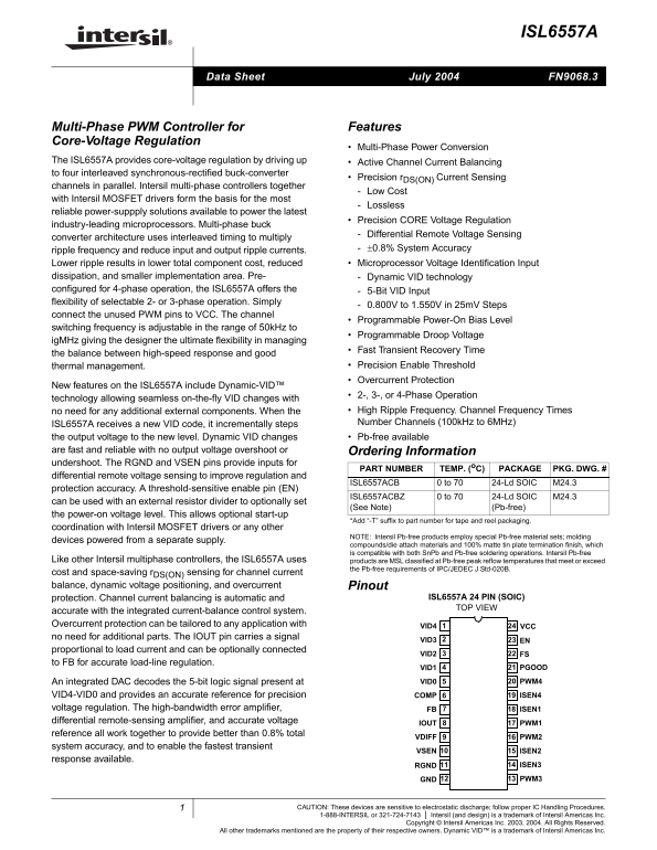
Page 1 Text Content
ISL6557A
July 2004 FN9068.3Data Sheet
Multi-Phase PWM Controller for Features Core-Voltage Regulation
Multi-Phase Power Conversion
The ISL6557A provides core-voltage regulation by driving up Active Channel Current Balancing to four interleaved synchronous-rectified buck-converter
Precision r DS(ON) Current Sensing
channels in parallel. Intersil multi-phase controllers together
Low Cost
with Intersil MOSFET drivers form the basis for the most
Lossless
reliable power-suppply solutions available to power the latest
Precision CORE Voltage Regulation
industry-leading microprocessors. Multi-phase buck
Differential Remote Voltage Sensing
converter architecture uses interleaved timing to multiply
ripple frequency and reduce input and output ripple currents. ±0.8% System Accuracy
Lower ripple results in lower total component cost, reduced Microprocessor Voltage Identification Input dissipation, and smaller implementation area. Pre- Dynamic VID technology configured for 4-phase operation, the ISL6557A offers the 5-Bit VID Input flexibility of selectable 2- or 3-phase operation. Simply
0.800V to 1.550V in 25m V Steps
connect the unused PWM pins to VCC. The channel
Programmable Power-On Bias Level
switching frequency is adjustable in the range of 50k Hz to
Programmable Droop Voltage
ig MHz giving the designer the ultimate flexibility in managing
Fast Transient Recovery Time
the balance between high-speed response and good
thermal management. Precision Enable Threshold Overcurrent Protection
New features on the ISL6557A include Dynamic-VID™
2-, 3-, or 4-Phase Operation
technology allowing seamless on-the-fly VID changes with
no need for any additional external components. When the High Ripple Frequency. Channel Frequency Times ISL6557A receives a new VID code, it incrementally steps Number Channels (100k Hz to 6MHz)
the output voltage to the new level. Dynamic VID changes Pb-free available are fast and reliable with no output voltage overshoot or Ordering Information undershoot. The RGND and VSEN pins provide inputs for
PART NUMBER TEMP. (o C) PACKAGE PKG. DWG. #
differential remote voltage sensing to improve regulation and
ISL6557ACB 0 to 70 24-Ld SOIC M24.3
protection accuracy. A threshold-sensitive enable pin (EN)
ISL6557ACBZ 0 to 70 24-Ld SOIC M24.3
can be used with an external resistor divider to optionally set
(See Note) (Pb-free)
the power-on voltage level. This allows optional start-up
*Add “-T” suffix to part number for tape and reel packaging.
coordination with Intersil MOSFET drivers or any other
NOTE: Intersil Pb-free products employ special Pb-free material sets; molding
devices powered from a separate supply.
compounds/die attach materials and 100% matte tin plate termination finish, which is compatible with both Sn Pb and Pb-free soldering operations. Intersil Pb-free
Like other Intersil multiphase controllers, the ISL6557A uses products are MSL classified at Pb-free peak reflow temperatures that meet or exceed
the Pb-free requirements of IPC/JEDEC J Std-020B.
cost and space-saving r DS(ON) sensing for channel current balance, dynamic voltage positioning, and overcurrent Pinout
protection. Channel current balancing is automatic and ISL6557A 24 PIN (SOIC) TOP VIEW
accurate with the integrated current-balance control system. Overcurrent protection can be tailored to any application with VID4
no need for additional parts. The IOUT pin carries a signal
VID3 EN
proportional to load current and can be optionally connected
VID2 FS
to FB for accurate load-line regulation.
VID1 PGOOD
An integrated DAC decodes the 5-bit logic signal present at VID0 PWM4
VID4-VID0 and provides an accurate reference for precision COMP ISEN4 voltage regulation. The high-bandwidth error amplifier, FB ISEN1 differential remote-sensing amplifier, and accurate voltage
IOUT PWM1
reference all work together to provide better than 0.8% total
VDIFF PWM2
system accuracy, and to enable the fastest transient
VSEN ISEN2
response available.
RGND ISEN3
GND PWM3
CAUTION: These devices are sensitive to electrostatic discharge; follow proper IC Handling Procedures.
1-888-INTERSIL or 321-724-7143 Intersil (and design) is a trademark of Intersil Americas Inc. Copyright © Intersil Americas Inc. 2003, 2004. All Rights Reserved.
All other trademarks mentioned are the property of their respective owners. Dynamic VID™ is a trademark of Intersil Americas Inc.
Page Summary Contents For Intel(Intersil) ISL6557A Data Sheet
Manual Details
| Brand | Intel |
|---|---|
| Pages | 19 |
| File Size | 540.64 KB |
| Published | May 29, 2026 |
Enter the captcha to get the download link:

Frequently Asked Questions
What types of voltage regulation does the ISL6557A provide?
It provides core-voltage regulation and dynamic VID technology for seamless on-the-fly changes.
How can I adjust the power-on behavior of this controller?
The EN pin allows setting the power-on voltage level using an external resistor divider, offering optional start-up coordination.
How does the ISL6557A improve efficiency and output quality?
It uses differential remote voltage sensing and interleaved timing to reduce input/output ripple current and increase system accuracy (better than ±0.8%).
Can this controller support different operation phases?
Yes, it supports 2-, 3-, or 4-phase operation with selectable flexibility.