Intel INTERSIL - ISL6545, ISL6545A Data Sheet
Summary
The ISL6545/ISL6545A is a highly integrated, voltage-mode synchronous buck DC/DC stepdown controller designed for robust power conversion. It excels at delivering precise, regulated output power from 5V or 12V supplies, featuring fast transient response and comprehensive protection schemes like selectable soft-start and overcurrent monitoring. This manual provides detailed specifications covering its single-loop control design, board diagrams, and wide range of applications. Ideal for engineers designing power solutions for microprocessors, embedded systems, memory buses (DDR), industrial controls, and general low-voltage distributed power supplies.
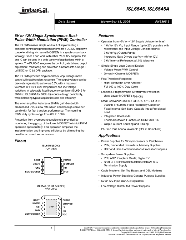
Page 1 Text Content
ISL6545, ISL6545A
November 15, 2006 FN6305.3Data Sheet
5V or 12V Single Synchronous Buck Features Pulse-Width Modulation (PWM) Controller
Operates from +5V or +12V Supply Voltage (for bias)
The ISL6545 makes simple work out of implementing a 1.0V to 12V VIN Input Range (up to 20V possible with complete control and protection scheme for a DC/DC stepdown restrictions; see Input Voltage Considerations) converter driving N-channel MOSFETs in a synchronous buck 0.6V to VIN Output Range topology. Since it can work with either 5V or 12V supplies, this Integrated Gate Drivers use VCC (5V to 12V) one IC can be used in a wide variety of applications within a
0.6V Internal Reference; ±1.0% tolerance
system. The ISL6545 integrates the control, gate drivers, output
Simple Single-Loop Control Design
adjustment, monitoring and protection functions into a single 8
Voltage-Mode PWM Control
Ld SOIC or 10 Ld DFN package.
Drives N-Channel MOSFETs
The ISL6545 provides single feedback loop, voltage-mode
Fast Transient Response
control with fast transient response. The output voltage can be
precisely regulated to as low as 0.6V, with a maximum High-Bandwidth Error Amplifier tolerance of ±1.0% over temperature and line voltage Full 0% to 100% Duty Cycle
variations. A selectable fixed frequency oscillator (ISL6545 for
Lossless, Programmable Overcurrent Protection
300k Hz; ISL6545A for 600k Hz) reduces design complexity,
Uses Lower MOSFET’s r DS(ON)
while balancing typical application cost and efficiency.
Small Converter Size in 8 Ld SOIC or 10 Ld DFN
The error amplifier features a 20MHz gain-bandwidth
300k Hz or 600k Hz Fixed Frequency Oscillator
product and 9V/μs slew rate which enables high converter
Fixed Internal Soft-Start, Capable into a Pre-biased
bandwidth for fast transient performance. The resulting
PWM duty cycles range from 0% to 100%.
Integrated Boot Diode
Protection from overcurrent conditions is provided by Enable/Shutdown Function on COMP/SD Pin monitoring the r DS(ON) of the lower MOSFET to inhibit PWM Output Current Sourcing and Sinking operation appropriately. This approach simplifies the
Pb-Free Plus Anneal Available (Ro HS Compliant)
implementation and improves efficiency by eliminating the need for a current sense resistor.
Applications
Pinout Power Supplies for Microprocessors or Peripherals
ISL6545 (SOIC) PCs, Embedded Controllers, Memory Supplies
TOP VIEW DSP and Core Communications Processor Supplies
Subsystem Power Supplies PCI, AGP; Graphics Cards; Digital TV
BOOT PHASE
SSTL-2 and DDR/DDR2/DDR3 SDRAM Bus
UGATE COMP/SD
Termination Supply
GND FB
Cable Modems, Set Top Boxes, and DSL Modems
LGATE/OCSET VCC
Industrial Power Supplies; General Purpose Supplies 5V or 12V-Input DC/DC Regulators ISL6545 (10 LD 3x3 DFN) Low-Voltage Distributed Power Supplies
TOP VIEW
1BOOT PHASE
UGATE
COMP/SD
N/C GND FB
5LGATE/OCSET VCC
CAUTION: These devices are sensitive to electrostatic discharge; follow proper IC Handling Procedures.
1-888-INTERSIL or 1-888-468-3774 Intersil (and design) is a registered trademark of Intersil Americas Inc.
Copyright © Intersil Americas Inc. 2006. All Rights Reserved
All other trademarks mentioned are the property of their respective owners.
Page Summary Contents For Intel INTERSIL - ISL6545, ISL6545A Data Sheet
Manual Details
| Brand | Intel |
|---|---|
| Pages | 16 |
| File Size | 272.97 KB |
| Published | May 31, 2026 |
Enter the captcha to get the download link:

Frequently Asked Questions
What is the recommended input supply range (V IN)?
The unit operates from +5V or +12V for bias and supports an input voltage range up to 20V.
How does it achieve fast transient response?
It features a high-bandwidth error amplifier (20MHz) with a 9V/μs slew rate and fixed internal soft-start.
What types of applications can the ISL6545 power?
It is suitable for diverse supplies, including microprocessors, peripherals (PCs, embedded controllers), and communications processor supplies.
Is specialized measurement equipment needed for this design?
The design simplifies implementation by eliminating the need for a current sense resistor using output current sourcing and sinking operation.