# A B C D E F G H I J K L M N O P Q R S T U V W X Y Z

Intel Intersil EL9200, EL9201, EL9202 Data Sheet

Summary

These highly precise programmable V amplifiers (EL9200, EL9201, EL9202) are designed for use in TFT-LCD display applications across monitors and TVs. Featuring adjustable sink current capabilities and internal EEPROM memory, these components allow engineers to precisely control video outputs with high bandwidth and reliability. This documentation provides a comprehensive datasheet covering technical specifications, package details, pinouts, absolute maximum ratings, and application guidelines needed for system integration. Ideal for electronics designers developing advanced display hardware.
📄 Preview PAGE OF 14

Page 1 Text Content

查询EL9200供应商

EL9200, EL9201, EL9202

Data Sheet April 7, 2005 FN7438.0

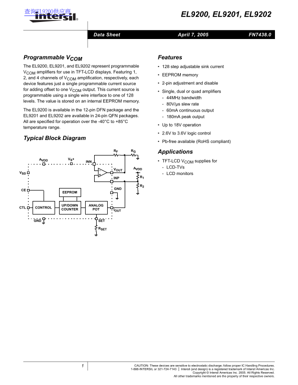
Programmable VCOM Features The EL9200, EL9201, and EL9202 represent programmable 128 step adjustable sink current VCOM amplifiers for use in TFT-LCD displays. Featuring 1,

EEPROM memory

2, and 4 channels of VCOM amplification, respectively, each

device features just a single programmable current source 2-pin adjustment and disable

for adding offset to one VCOM output. This current source is

Single, dual or quad amplifiers

programmable using a single wire interface to one of 128

44MHz bandwidth

levels. The value is stored on an internal EEPROM memory.

80V/µs slew rate

The EL9200 is available in the 12-pin DFN package and the 60m A continuous output EL9201 and EL9202 are available in 24-pin QFN packages. 180m A peak output All are specified for operation over the -40°C to +85°C

Up to 18V operation

temperature range.

2.6V to 3.6V logic control

Typical Block Diagram

Pb-free available (Ro HS compliant)

RF RG

Applications

AVDD VS+

INN TFT-LCD VCOM supplies for AVDD LCD-TVs

LCD monitors

EEPROM

UP/DOWN ANALOG

CONTROL

COUNTER POTCTL IOUT

GND SET

CAUTION: These devices are sensitive to electrostatic discharge; follow proper IC Handling Procedures.

1-888-INTERSIL or 321-724-7143 Intersil (and design) is a registered trademark of Intersil Americas Inc. Copyright © Intersil Americas Inc. 2005. All Rights Reserved. All other trademarks mentioned are the property of their respective owners.

Page Summary Contents For Intel Intersil EL9200, EL9201, EL9202 Data Sheet

Page 1 查询EL9200供应商 EL9200, EL9201, EL9202 Data Sheet April 7, 2005 FN7438.0 Programmable VCOM Features The EL9200, EL9201, and EL9202 represent programmable 128 step adjustable sink current VCOM amplifiers f...
Page 2 EL9200, EL9201, EL9202 Pinouts EL9200 EL9201 EL9202 (12-PIN DFN) (24-PIN QFN) (24-PIN QFN) TOP VIEW TOP VIEW TOP VIEW VINA- VS+ NC NC VOUTA VOUTB GND VOUTA NC VOUTA VOUTD VOUTC VINA+ SET VINB+ VS+ VIN...
Page 3 EL9200, EL9201, EL9202 Absolute Maximum Ratings (TA = 25°C) VS+ Supply Voltage between VS+ and GND . . . . . . . . . . . . . .18V AVDD . . . . . . . . . . . . . . . . . . . . . . . . . . . . . . . . ....
Page 4 EL9200, EL9201, EL9202 Electrical Specifications VSD = 3V, VS+ = 15V, AVDD = 15V, RSET = 24.9kΩ, and TA = 25°C unless otherwise specified PARAMETER DESCRIPTION CONDITION MIN TYP MAX UNIT SETZSE SET Ze...
Page 5 EL9200, EL9201, EL9202 Pin Descriptions PIN IN/OUT DESCRIPTION EQUIVALENT CIRCUIT VINX- Input Amplifier X inverting input, where: X = A for EL9200 X = A, B for EL9201 X = A, B, C, D for EL9202 CIRCUIT...
Page 6 EL9200, EL9201, EL9202 Amplifier Typical Performance Curves IN PU FF SE VO LT (m V) TI TY (A PL IF IE S) TI TY (A PL IF IE S) VS=5V TYPICAL VS=5V TA=25°C PRODUCTION -1 DISTRIBUTION INPUT OFFSET VOLTAG...
Page 7 EL9200, EL9201, EL9202 Amplifier Typical Performance Curves IS TO TI (d IF FE EN TI IN PE -L IN (d VS=±5V VS=±V RL=1kΩ TEMPERATURE (°C) TEMPERATURE (°C) FIGURE 7. OPEN-LOOP GAIN vs TEMPERATURE FIGURE ...
Page 8 EL9200, EL9201, EL9202 Amplifier Typical Performance Curves (d TP IM PE (Ω IT (N LI ZE ) ( d B VS=5V AV=1 CLOAD=0p F VS=5V AV=1 RL=1kΩ FREQUENCY (Hz) FREQUENCY (Hz) FIGURE 13. FREQUENCY RESPONSE FOR V...
Page 9 EL9200, EL9201, EL9202 Amplifier Typical Performance Curves VE SH VO LT IS (n V/ √H z) DUAL MEASURED CH A TO B QUAD MEASURED CH A TO D OR B TO C OTHER COMBINATIONS YIELD -80 IMPROVED REJECTION VS=5V -...
Page 10 EL9200, EL9201, EL9202 Amplifier Typical Performance Curves PO ER IS SI PA TI (W JEDEC JESD51-7 HIGH EFFECTIVE THERMAL CONDUCTIVITY TEST BOARD - QFN EXPOSED JEDEC JESD51-3 LOW EFFECTIVE THERMAL DIEPAD...
Page 11 EL9200, EL9201, EL9202 more than 200µs. The output sink current will decrease and Since the internal comparators come up in an unknown the VCOM level will increase by one LSB. state, the very first CT...
Page 12 EL9200, EL9201, EL9202 Non-Volatile Memory (EEPROM) Short-Circuit Current Limit Programming The amplifiers will limit the short circuit current to ±180m A if the output is directly shorted to the posi...
Page 13 EL9200, EL9201, EL9202 Replacing Existing Mechanical Potentiometer Circuits Figures 29 and 30 show the common adjustment mechanical circuits and equivalent replacement with the EL920X. AVDD AVDD RF RG...
Page 14 EL9200, EL9201, EL9202 QFN Package Outline Drawing NOTE: The package drawing shown here may not be the latest version. To check the latest revision, please refer to the Intersil website at http://www....

Manual Details

Brand Intel
Pages 14
File Size 462.46 KB
Published May 31, 2026
84 views

Enter the captcha to get the download link:

captcha

Frequently Asked Questions

What is the operational temperature range for these devices?

The operating temperature range is specified from -40°C to +85°C.

Which package does EL9200 use, and which packages are available for EL9201 and EL9202?

EL9200 is available in a 12-pin DFN package, while EL9201 and EL9202 come in 24-pin QFN packages.

What type of failure do these devices require proper handling procedures for?

These devices are sensitive to electrostatic discharge and require following proper IC Handling Procedures.