Intel Intersil EL5164, EL5165, EL5364 Data Handbook
Summary
Elevate your signal integrity with high-speed current feedback amplifiers from the EL5164 family. Featuring a 600MHz bandwidth, rapid slew rates, and extremely low power consumption, these monolithic ICs are ideal for demanding video transmission and monitoring applications. This technical guide provides comprehensive specifications, operational parameters, and detailed package options, catering to engineers designing portable, battery-powered, or industrial-grade electronics needing reliable performance in constrained environments.
Page 1 Text Content
查询EL5164供应商
EL5164, EL5165, EL5364
Data Sheet June 22, 2004 FN7389.3
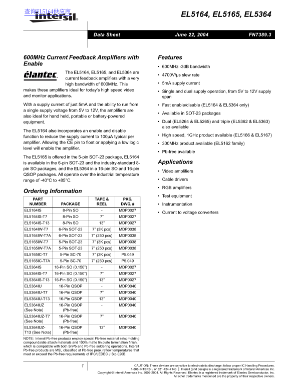
600MHz Current Feedback Amplifiers with Features Enable
600MHz -3d B bandwidth
The EL5164, EL5165, and EL5364 are
4700V/µs slew rate
current feedback amplifiers with a very
high bandwidth of 600MHz. This 5m A supply current
makes these amplifiers ideal for today’s high speed video
Single and dual supply operation, from 5V to 12V supply
and monitor applications. span
With a supply current of just 5m A and the ability to run from Fast enable/disable (EL5164 & EL5364 only) a single supply voltage from 5V to 12V, the amplifiers are
Available in SOT-23 packages
also ideal for hand held, portable or battery-powered
equipment. Dual (EL5264 & EL5265) and triple (EL5362 & EL5363) also available
The EL5164 also incorporates an enable and disable
High speed, 1GHz product available (EL5166 & EL5167)
function to reduce the supply current to 100µA typical per amplifier. Allowing the CE pin to float or applying a low logic 300MHz product available (EL5162 family) level will enable the amplifier.
Pb-free available
The EL5165 is offered in the 5-pin SOT-23 package, EL5164
is available in the 6-pin SOT-23 and the industry-standard 8- Applications
pin SO packages, and the EL5364 in a 16-pin SO and 16-pin
Video amplifiers
QSOP packages. All operate over the industrial temperature
range of -40°C to +85°C. Cable drivers RGB amplifiers
Ordering Information
Test equipment
PART TAPE & PKG. NUMBER PACKAGE REEL DWG. # Instrumentation EL5164IS 8-Pin SO MDP0027
Current to voltage converters
EL5164IS-T7 8-Pin SO 7” MDP0027 EL5164IS-T13 8-Pin SO 13” MDP0027 EL5164IW-T7 6-Pin SOT-23 7” (3K pcs) MDP0038 EL5164IW-T7A 6-Pin SOT-23 7” (250 pcs) MDP0038 EL5165IW-T7 5-Pin SOT-23 7” (3K pcs) MDP0038 EL5165IW-T7A 5-Pin SOT-23 7” (250 pcs) MDP0038 EL5165IC-T7 5-Pin SC-70 7” (3K pcs) P5.049 EL5165IC-T7A 5-Pin SC-70 7” (250 pcs) P5.049 EL5364IS 16-Pin SO (0.150”) MDP0027 EL5364IS-T7 16-Pin SO (0.150”) 7” MDP0027 EL5364IS-T13 16-Pin SO (0.150”) 13” MDP0027 EL5364IU 16-Pin QSOP MDP0040 EL5364IU-T7 16-Pin QSOP 7” MDP0040 EL5364IU-T13 16-Pin QSOP 13” MDP0040 EL5364IUZ 16-Pin QSOP MDP0040 (See Note) (Pb-free) EL5364IUZ-T7 16-Pin QSOP 7” MDP0040 (See Note) (Pb-free) EL5364IUZ- 16-Pin QSOP 13” MDP0040 T13 (See Note) (Pb-free) NOTE: Intersil Pb-free products employ special Pb-free material sets; molding compounds/die attach materials and 100% matte tin plate termination finish, which is compatible with both Sn Pb and Pb-free soldering operations. Intersil Pb-free products are MSL classified at Pb-free peak reflow temperatures that meet or exceed the Pb-free requirements of IPC/JEDEC J Std-020B.
CAUTION: These devices are sensitive to electrostatic discharge; follow proper IC Handling Procedures.
1-888-INTERSIL or 321-724-7143 Intersil (and design) is a registered trademark of Intersil Americas Inc.
Copyright © Intersil Americas Inc. 2002-2004. All Rights Reserved. Elantec is a registered trademark of Elantec Semiconductor, Inc.
All other trademarks mentioned are the property of their respective owners.
Page Summary Contents For Intel Intersil EL5164, EL5165, EL5364 Data Handbook
Manual Details
| Brand | Intel |
|---|---|
| Pages | 12 |
| File Size | 405.76 KB |
| Published | May 30, 2026 |
Enter the captcha to get the download link:

Frequently Asked Questions
What is the bandwidth of these current feedback amplifiers?
The devices offer a high bandwidth of 600MHz (-3dB).
Do they support different supply voltages?
They can operate using single or dual supply voltages, ranging from 5V to 12V.
What is the recommended temperature range for use?
They are designed to operate over the industrial cable drivers' temperature range of -40°C to +85°C.
How can I reduce the power current when not in active use?
The EL5164 and EL5364 include an enable function, which allows you to minimize supply current to 100µA typically per amplifier.