ISL90726 Data Handbook by Intel Silicon (Intersil)
Summary
The ISL90726 is a low-power, solid-state potentiometer featuring 128 digitally controlled taper points via the I²C serial bus interface. This versatile component provides precise resistance adjustment without moving parts, making it an excellent replacement for mechanical potentiometers. The technical manual details its operation and specifications, offering guidance on applications such as sensor calibration (pressure/temperature), LCD brightness control, chemical sensing, and laser biasing. It is designed for engineers requiring accurate, reliable signal control in embedded systems.
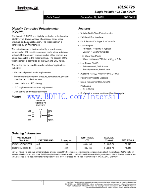
Page 1 Text Content
ISL90726
Single Volatile 128-Tap XDCP
December 22, 2005 FN8244.3Data Sheet
Digitally Controlled Potentiometer Features (XDCP™)
Volatile Solid-State Potentiometer
The Intersil ISL90726 is a digitally controlled potentiometer
I2C Serial Bus Interface
(XDCP). The device consists of a resistor array, wiper
switches, and a control section. The wiper position is DCP Terminal Voltage, 2.7V to 5.5V
controlled by an I2C interface.
Low Tempco The potentiometer is implemented by a resistor array Rheostat - 45 ppm/°C typical composed of 127 resistive elements and a wiper switching Divider - 15 ppm/°C typical
network. Between each element and at either end are tap
128 Wiper Tap Points
points accessible to the wiper terminal. The position of the
Wiper resistance 70Ω typ at VCC = 3.3V
wiper element is controlled by the SDA and SCL inputs.
Low Power CMOS
The device can be used in a wide variety of applications
Active current, 200µA max
including:
Standby current, 500n A max
Mechanical potentiometer replacement
Available RTOTAL Values = 50kΩ, 10kΩ
Transducer adjustment of pressure, temperature, position,
Power on Preset to Midscale
chemical, and optical sensors
Direct replacement for AD5246
Laser diode and LED biasing
Packaging
LCD brightness and contrast adjustment
6 Ld SC-70
Gain control and offset adjustment
Pb-free plus anneal available (Ro HS compliant)
Pinout www.BDTIC.com/Intersil
ISL90726 (6 LD SC-70) TOP VIEW
VDD RL
GND RW
SCL SDA
Ordering Information
PART NUMBER TEMP RANGE PACKAGE (See Note) PART MARKING RTOTAL (Ω) (°C) (Pb-free) PKG. DWG. #
ISL90726WIE627Z-TK ANF 10K -40 to +85 6 Ld SC-70 P6.049
ISL90726UIE627Z-TK ANG 50K -40 to +85 6 Ld SC-70 P6.049
NOTE: Intersil Pb-free plus anneal products employ special Pb-free material sets; molding compounds/die attach materials and 100% matte tin plate termination finish, which are Ro HS compliant and compatible with both Sn Pb and Pb-free soldering operations. Intersil Pb-free products are MSL classified at Pb-free peak reflow temperatures that meet or exceed the Pb-free requirements of IPC/JEDEC J STD-020.
CAUTION: These devices are sensitive to electrostatic discharge; follow proper IC Handling Procedures. 1-888-INTERSIL or 1-888-468-3774 Intersil (and design) is a registered trademark of Intersil Americas Inc. XDCP is a trademark of Intersil Americas Inc. Copyright Intersil Americas Inc. 2005. All Rights Reserved
All other trademarks mentioned are the property of their respective owners.
Page Summary Contents For ISL90726 Data Handbook by Intel Silicon (Intersil)
Manual Details
| Brand | Intel |
|---|---|
| Pages | 8 |
| File Size | 221.51 KB |
| Published | May 30, 2026 |
Enter the captcha to get the download link:

Frequently Asked Questions
How is the wiper position controlled?
The wiper element position is digitally controlled via an I²C Serial Bus Interface using the SDA and SCL inputs.
What types of electronics benefits from this component?
It can be used for LCD brightness adjustment, laser diode/LED biasing, or direct replacement for mechanical potentiometers.
Are there different resistance values available?
Yes, the ISL90726 is available in 50kΩ and 10kΩ resistor array values.
What handling precautions must be observed during use?
The devices are sensitive to electrostatic discharge; proper IC Handling Procedures must be followed carefully.