HP Scitex FB10000 Industrial Printer Geffen TS Error 67024
Summary
This essential technical guide provides comprehensive troubleshooting workflows for industrial printing equipment errors, specifically addressing Error ID 67024 concerning the rear rising media detector. Designed for service technicians and skilled operators, this manual covers diagnosing varied issues including mechanical failures, poor substrate quality, sensor misalignment, and connectivity faults. It details step-by-step systematic checks, necessary recalibration procedures, and recommended solutions to ensure optimal machine function and minimize downtime.
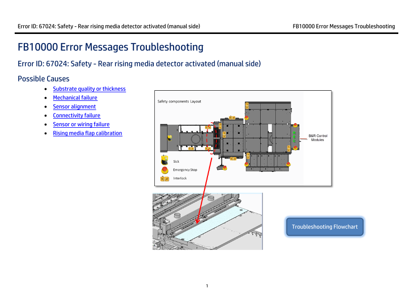
Page 1 Text Content
Error ID: 67024: Safety - Rear rising media detector activated (manual side) FB10000 Error Messages Troubleshooting
FB10000 Error Messages Troubleshooting Error ID: 67024: Safety - Rear rising media detector activated (manual side) Possible Causes • Substrate quality or thickness • Mechanical failure • Sensor alignment • Connectivity failure • Sensor or wiring failure • Rising media flap calibration
Troubleshooting Flowchart
Page Summary Contents For HP Scitex FB10000 Industrial Printer Geffen TS Error 67024
Manual Details
| Brand | HP |
|---|---|
| Pages | 9 |
| File Size | 496.36 KB |
| Published | June 18, 2026 |
Enter the captcha to get the download link:

Frequently Asked Questions
What are the initial steps if I receive Error ID: 67024?
First, press the Reset button and click Refresh; if it persists, open the UV door to pull out any stuck media before checking substrate quality.
If the rising media flap is stiff or not moving smoothly, what should I check?
Check the pivot pin for mechanical problems that prevent smooth movement; lubrication may be required.
How can I troubleshoot sensor connectivity issues?
Open the REC door and verify the status of green LEDs 9 & 10 on the 2SDI3 B&R module. If they are off, check the physical connection between the sensor and the module.
What process is needed to properly calibrate the sensor?
Use jigs no’1 or no’2. Slide the jig until the RM flap rises above it, then adjust the bracket location until the sensor LED turns on; repeat for all sensors.