Fairchild FDC6331L Integrated Load Switch Data Manual
Summary
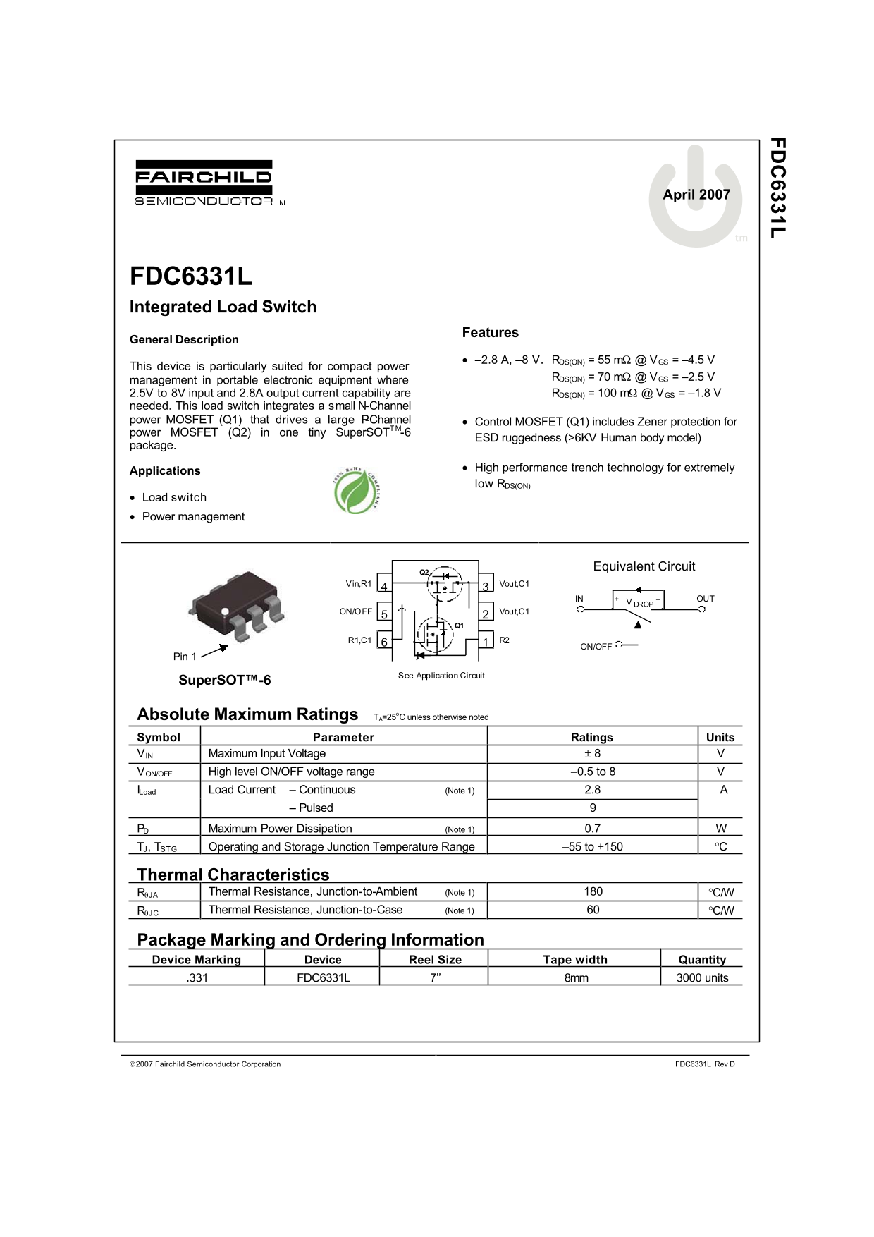
The FDC6331L is a compact Integrated Load Switch designed for efficient power management in portable electronic equipment. It features industry-leading low R_DS(ON) and integrated protection across a tiny SuperSOT-6 package, making it ideal for applications requiring reliable current handling up to 2.8A. This manual provides comprehensive technical specifications, detailed application circuits, thermal modeling data, and electrical characteristics necessary for designers building advanced battery-powered or compact device systems.
Page 1 Text Content
FD 6331L
August
April 2007
FDC6331L Integrated Load Switch
Features
General Description
–2.8 A, –8 V. RDS(ON) = 55 m @ VGS = –4.5 V
This device is particularly suited for compact power
RDS(ON) = 70 m @ VGS = –2.5 V
management in portable electronic equipment where
2.5V to 8V input and 2.8A output current capability are RDS(ON) = 100 @ VGS = –1.8 V
needed. This load switch integrates a small N-Channel power MOSFET (Q1) that drives a large P-Channel Control MOSFET (Q1) includes Zener protection for power MOSFET (Q2) in one tiny Super SOTTM-6
ESD ruggedness (>6KV Human body model)
package.
High performance trench technology for extremely
Applications
low RDS(ON)
Load switch Power management
D2 Equivalent Circuit
Vin,R1 Vout,C1
–IN OUT
ON/OFF Vout,C1
Super SOT -6TM ON/OFF
Pin 1
See Application Circuit
Super SOT™-6
Absolute Maximum Ratings TA=25o C unless otherwise noted Symbol Parameter Ratings Units VIN Maximum Input Voltage 8 VON/OFF High level ON/OFF voltage range –0.5 to 8 ILoad Load Current – Continuous (Note 1) 2.8
– Pulsed
PD Maximum Power Dissipation (Note 1) 0.7 TJ, TSTG Operating and Storage Junction Temperature Range –55 to +150
Thermal Characteristics
JA Thermal Resistance, Junction-to-Ambient (Note 1) C/W
JC Thermal Resistance, Junction-to-Case (Note 1) C/W
Package Marking and Ordering Information Device Marking Device Reel Size Tape width Quantity
.331 FDC6331L 7’’ 8mm 3000 units
Fairchild Semiconductor Corporation FDC6331L Rev D
Page Summary Contents For Fairchild FDC6331L Integrated Load Switch Data Manual
Manual Details
| Brand | Fairchild |
|---|---|
| Pages | 4 |
| File Size | 91.17 KB |
| Published | July 06, 2026 |
Enter the captcha to get the download link:

Frequently Asked Questions
What input voltage range does this load switch support?
It supports an input voltage (VIN) from –8 V up to 8 V.
How is the device packaged and what safety feature is included?
It comes in a SuperSOT-6 package and includes Zener protection for both MOSFETs.
What should I use for additional in-rush current control?
Add components R2 and C1 to the circuit for better in-rush current control.