Fairchild FDC6329L Integrated Load Switch Data Manual
Summary
The FDC6329L is a high-performance load switch engineered for efficient power management in compact, portable electronic equipment. It integrates dual MOSFET technology into a tiny SuperSOT package, ensuring superior thermal performance and ultra-low on-resistance crucial for battery-powered devices. This technical datasheet provides application engineers with comprehensive data covering electrical performance variation, transient thermal response modeling, and detailed guidelines on component selection, making it the essential resource for reliably integrating robust power switching solutions into modern, space-constrained designs.
Page 1 Text Content
November 1998
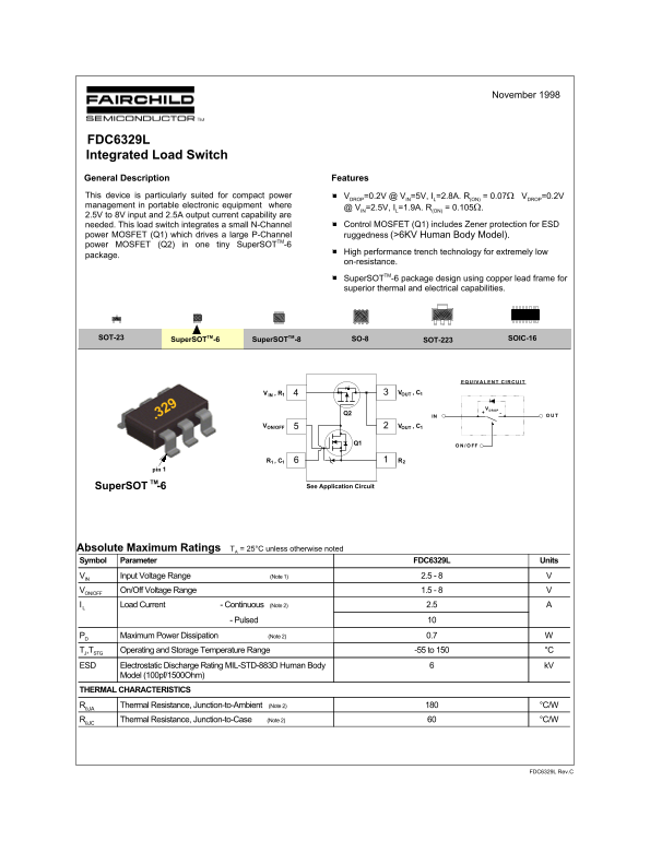
FDC6329L Integrated Load Switch General Description Features This device is particularly suited for compact power VDROP=0.2V @ VIN=5V, IL=2.8A. R(ON) = 0.07Ω VDROP=0.2V management in portable electronic equipment where
@ VIN=2.5V, IL=1.9A. R(ON) = 0.105Ω.
2.5V to 8V input and 2.5A output current capability are
needed. This load switch integrates a small N-Channel Control MOSFET (Q1) includes Zener protection for ESD
power MOSFET (Q1) which drives a large P-Channel ruggedness (>6KV Human Body Model). power MOSFET (Q2) in one tiny Super SOTTM-6
High performance trench technology for extremely low
package.
on-resistance. Super SOTTM-6 package design using copper lead frame for superior thermal and electrical capabilities.
SOT-23 Super SOTTM-8 SOIC-16SO-8
SOT-223Super SOTTM-6
V , RIN V , COUT
VDROP+
.329 IN ON/OFFV V , COUT
Q1 FF
Super SOT -6TM See Application Circuit
Absolute Maximum Ratings TA = 25°C unless otherwise noted Symbol Parameter FDC6329L Units VIN Input Voltage Range (Note 1) 2.5 - 8 VON/OFF On/Off Voltage Range 1.5 - 8 I L Load Current - Continuous (Note 2) 2.5
- Pulsed 10
PD Maximum Power Dissipation (Note 2) 0.7 TJ,TSTG Operating and Storage Temperature Range -55 to 150 °C ESD Electrostatic Discharge Rating MIL-STD-883D Human Body k V
Model (100pf/1500Ohm)
THERMAL CHARACTERISTICS
RθJA Thermal Resistance, Junction-to-Ambient (Note 2) °C/W RθJC Thermal Resistance, Junction-to-Case (Note 2) °C/W
FDC6329L Rev.C
Page Summary Contents For Fairchild FDC6329L Integrated Load Switch Data Manual
Manual Details
| Brand | Fairchild |
|---|---|
| Pages | 4 |
| File Size | 141.41 KB |
| Published | June 18, 2026 |
Enter the captcha to get the download link:

Frequently Asked Questions
What package type should be used for optimal thermal and electrical performance?
The SuperSOT-6 package design, using copper lead frame, provides superior thermal and electrical capabilities.
How can I control in-rush current when implementing this load switch?
For additional in-rush current control, you can add a capacitor C1 up to 1000pF.
What is the recommended range for R2 (slew rate control)?
Select R2 in the range of 1k - 4.7kW for proper slew rate control.