MAXIM INTEGRATED PRODUCTS Stand-Alone, Switch-Mode Li+ Battery Charger with Internal 28V Switch Owner's Manual
Summary
The MAX1758 is a sophisticated, stand-alone switch-mode charger designed for safely powering one to four lithium-ion (Li+) battery cells. This manual details the comprehensive operation and integration of the charger, covering advanced features such as up to 28V input support, continuous temperature monitoring, built-in overcharge protection, and programmable charging current/timers. It is ideal for engineers designing portable electronics, hand-held instruments, or notebook computers that require reliable, multi-cell battery management solutions with minimal board space usage.
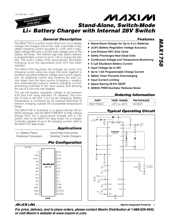
Page 1 Text Content
19-1752; Rev 1; 1/01
EVALUATION KIT AVAILABLE
Stand-Alone, Switch-Mode
Li+ Battery Charger with Internal 28V Switch General Description Features The MAX1758 is a switch-mode lithium-ion (Li+) battery Stand-Alone Charger for Up to 4 Li+ Batteries charger that charges one-to-four cells. It provides a reg-
±0.8% Battery Regulation Voltage Accuracy
ulated charging current accurate to ±10% and a regu-
lated voltage with only a ±0.8% total voltage error at the Low-Dropout 98% Duty Cycle
battery terminals. The internal high-side switch delivers
Safely Precharges Near-Dead Cells
a programmable current of up to 1.5A to charge the bat-
tery. The built-in safety timer automatically terminates Continuous Voltage and Temperature Monitoring
charging once the adjustable time limit has been
0.1µA Shutdown Battery Current
reached.
Input Voltage Up to 28V
The MAX1758 regulates the voltage set point and
charging current using two loops that work together to Up to 1.5A Programmable Charge Current
transition smoothly between voltage and current regula-
Safety Timer Prevents Overcharging
tion. An additional control loop monitors the total cur-
rent drawn from the input source (charging + system), Input Current Limiting
and automatically reduces battery-charging current,
Space-Saving 28-Pin SSOP
preventing overload of the input supply and allowing
300k Hz PWM Oscillator Reduces Noise
the use of a low-cost wall adapter. The per-cell battery regulation voltage is set between
4.0V and 4.4V using standard 1% resistors. The num- Ordering Information
ber of cells is set from 1-to-4 by pin strapping. Battery
temperature is monitored by an external thermistor to PART PIN-PACKAGETEMP. RANGE
prevent charging outside the acceptable temperature -40°C to +85°CMAX1758EAI 28 SSOP range. The MAX1758 is available in a space-saving 28-pin
Typical Operating Circuit
SSOP package. Use the MAX1758EVKIT to help reduce design time. For a stand-alone charger with a 14V
switch, refer to the MAX1757 data sheet. For a charger VIN 6V TO 28V
controller capable of up to 4A charging current, refer to
DCIN CSSP
the MAX1737 data sheet. SYSTEM
________________________Applications HSD LX
Li+ Battery Packs Hand-Held Instruments MAX1758
Notebook Computers Desktop Cradle Chargers ISETOUT BST
Pin Configuration
ISETIN
TOP VIEW
CELL CS
VL DCIN
ISETIN CSSP
ISETOUT CSSN
THM CCV THM
REF CCI
CCS Li+ BATTERY
MAX1758 THERM 1 TO 4 CELLS
GND CCS
VADJ BST
BATT CS
HSD LX
CCV FASTCHG
HSD LX
CELL PGND TIMER1 FULLCHG
TIMER1 SHDN
TIMER2 FAULT
TIMER2 FULLCHG
FAULT FASTCHG OFF SHDN
Maxim Integrated Products
For price, delivery, and to place orders, please contact Maxim Distribution at 1-888-629-4642, or visit Maxim’s website at www.maxim-ic.com.
Page Summary Contents For MAXIM INTEGRATED PRODUCTS Stand-Alone, Switch-Mode Li+ Battery Charger with Internal 28V Switch Owner's Manual
Manual Details
| Brand | Maxim Integrated |
|---|---|
| Pages | 17 |
| File Size | 224.38 KB |
| Published | May 26, 2026 |
Enter the captcha to get the download link:

Frequently Asked Questions
How do I configure the charger for a specific cell count?
The number of cells (1 to 4) is determined by pin strapping.
What are the limits for the input voltage?
The MAX1758 supports an Input Voltage range up to 28V.
Does it monitor temperature during charging?
Yes, battery temperature must be monitored using an external thermistor to ensure safe operation and prevent overheating.
How are the timer limits for various charge stages (full/fast) set?
Timer periods are controlled by connecting capacitors to the corresponding TIMER1 and TIMER2 input pins.