Vishay VTSR VSSR VSOR Molded, 25 or 50 Mil Pitch, Dual-In-Line Resistor Networks Owner's Manual and User Guide
Summary
Explore Vishay's line of thin film resistor networks—advanced electronic components designed for precision digital and analog circuits. This guide provides comprehensive details on VTSR, VSSR, and VSOR series, covering electrical specifications, packaging dimensions, and schematic configurations like differential terminators and pull-up/down resistors. It is the essential resource for electrical engineers and designers building high-stability, low-noise systems for specialized instrumentation.
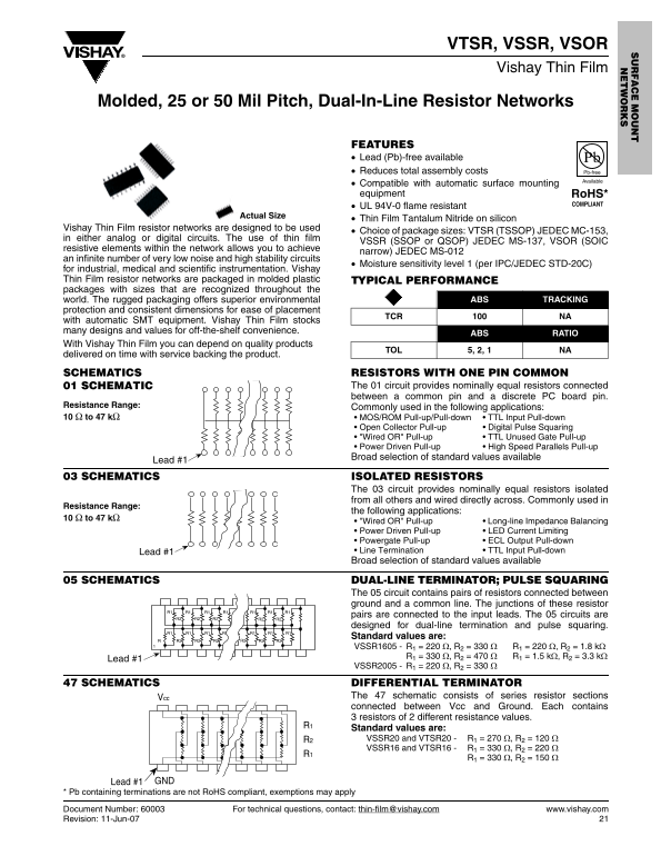
Page 1 Text Content
VTSR, VSSR, VSOR Vishay Thin Film
Molded, 25 or 50 Mil Pitch, Dual-In-Line Resistor Networks
FEATURES Lead (Pb)-free available Reduces total assembly costs Pb-free
Available
Compatible with automatic surface mounting equipment Ro HS*
COMPLIANT
UL 94V-0 flame resistant
Actual Size
Thin Film Tantalum Nitride on silicon
Vishay Thin Film resistor networks are designed to be used
Choice of package sizes: VTSR (TSSOP) JEDEC MC-153,
in either analog or digital circuits. The use of thin film
VSSR (SSOP or QSOP) JEDEC MS-137, VSOR (SOIC
resistive elements within the network allows you to achieve
narrow) JEDEC MS-012
an infinite number of very low noise and high stability circuits
Moisture sensitivity level 1 (per IPC/JEDEC STD-20C)
for industrial, medical and scientific instrumentation. Vishay Thin Film resistor networks are packaged in molded plastic TYPICAL PERFORMANCE packages with sizes that are recognized throughout the
world. The rugged packaging offers superior environmental ABS TRACKING
protection and consistent dimensions for ease of placement
TCR NA
with automatic SMT equipment. Vishay Thin Film stocks many designs and values for off-the-shelf convenience.
ABS RATIO
With Vishay Thin Film you can depend on quality products
TOL 5, 2, 1 NA
delivered on time with service backing the product. SCHEMATICS RESISTORS WITH ONE PIN COMMON
01 SCHEMATIC The 01 circuit provides nominally equal resistors connected between a common pin and a discrete PC board pin.
Resistance Range: Commonly used in the following applications: 10 Ω to 47 kΩ • MOS/ROM Pull-up/Pull-down • TTL Input Pull-down
• Open Collector Pull-up • Digital Pulse Squaring • "Wired OR" Pull-up • TTL Unused Gate Pull-up • Power Driven Pull-up • High Speed Parallels Pull-up Broad selection of standard values available
Lead #1
03 SCHEMATICS ISOLATED RESISTORS
The 03 circuit provides nominally equal resistors isolated from all others and wired directly across. Commonly used in
Resistance Range:
the following applications:
10 Ω to 47 kΩ
• "Wired OR" Pull-up • Long-line Impedance Balancing • Power Driven Pull-up • LED Current Limiting • Powergate Pull-up • ECL Output Pull-down Lead #1 • Line Termination • TTL Input Pull-down Broad selection of standard values available
05 SCHEMATICS DUAL-LINE TERMINATOR; PULSE SQUARING
The 05 circuit contains pairs of resistors connected between ground and a common line. The junctions of these resistor
pairs are connected to the input leads. The 05 circuits are
designed for dual-line termination and pulse squaring.
Standard values are:
VSSR1605 - R1 = 220 Ω, R2 = 330 Ω R1 = 220 Ω, R2 = 1.8 kΩ
Lead #1
VSSR2005 - R1 = 220 Ω, R2 = 330 Ω
47 SCHEMATICS DIFFERENTIAL TERMINATOR
Vcc The 47 schematic consists of series resistor sections connected between Vcc and Ground. Each contains 3 resistors of 2 different resistance values.
Standard values are: R2 VSSR20 and VTSR20 - R1 = 270 Ω, R2 = 120 Ω VSSR16 and VTSR16 - R1 = 330 Ω, R2 = 220 Ω
Lead #1 GND
* Pb containing terminations are not Ro HS compliant, exemptions may apply
Document Number: 60003 For technical questions, contact: [email protected] www.vishay.com
Revision: 11-Jun-07
Page Summary Contents For Vishay VTSR VSSR VSOR Molded, 25 or 50 Mil Pitch, Dual-In-Line Resistor Networks Owner's Manual and User Guide
Manual Details
| Brand | Vishay |
|---|---|
| Pages | 4 |
| File Size | 132.85 KB |
| Published | May 31, 2026 |
Enter the captcha to get the download link:

Frequently Asked Questions
What is the operating temperature range?
The operating temperature range is -55 °C to +125 °C.
Is this product suitable for automatic surface mounting (SMT)?
Yes, it is compatible with automatic surface mounting equipment like SMT machines.
What are the available resistance values and ranges?
The resistance range commonly used is 10 Ω to 47 kΩ. Tolerance options include ±5%, ±2%, or ±1%.
How powerful are the components?
The maximum power rating, depending on package size, can reach 1.4 W for the 24-pin package (at +70 °C).