Vishay Sprague 564R and 565R Series Cera-Mite User Guide and Owner's Manual
Summary
Discover Vishay Cera-Mite lower voltage ceramic disc capacitors in the 564R and 565R series. Designed for demanding applications such as lighting ballasts and SMPS, these high-performance components offer low losses, high stability, and reliable operation across a wide range of voltages (up to 7.5 kV DC). The manual provides comprehensive technical details, material specifications, capacitance tolerances (e.g., X7R, Y5V), and detailed ordering information for reliable system integration.
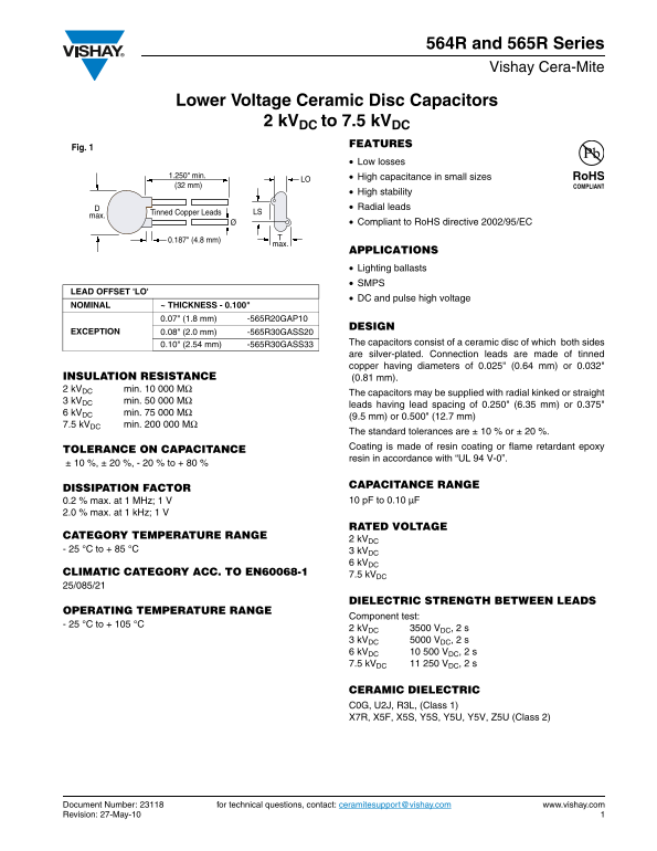
Page 1 Text Content
564R and 565R Series Vishay Cera-Mite
Lower Voltage Ceramic Disc Capacitors
2 k VDC to 7.5 k VDC
FEATURES
Fig. 1
Low losses LO1.250" min. High capacitance in small sizes
(32 mm)
High stability Radial leads
Tinned Copper Leads D LS
Compliant to Ro HS directive 2002/95/EC
0.187" (4.8 mm)
APPLICATIONS Lighting ballasts SMPS
LEAD OFFSET 'LO'
DC and pulse high voltage
NOMINAL ~ THICKNESS - 0.100"
0.07" (1.8 mm) -565R20GAP10
DESIGN
EXCEPTION 0.08" (2.0 mm) -565R30GASS20
0.10" (2.54 mm) -565R30GASS33 The capacitors consist of a ceramic disc of which both sides are silver-plated. Connection leads are made of tinned copper having diameters of 0.025" (0.64 mm) or 0.032"
INSULATION RESISTANCE (0.81 mm). 2 k VDC min. 10 000 MΩ
The capacitors may be supplied with radial kinked or straight
3 k VDC min. 50 000 MΩ
leads having lead spacing of 0.250" (6.35 mm) or 0.375"
6 k VDC min. 75 000 MΩ
(9.5 mm) or 0.500" (12.7 mm)
7.5 k VDC min. 200 000 MΩ
The standard tolerances are ± 10 % or ± 20 %. Coating is made of resin coating or flame retardant epoxy
TOLERANCE ON CAPACITANCE
resin in accordance with “UL 94 V-0”.
± 10 %, ± 20 %, - 20 % to + 80 %
CAPACITANCE RANGE
DISSIPATION FACTOR
0.2 % max. at 1 MHz; 1 V 10 p F to 0.10 µF
2.0 % max. at 1 k Hz; 1 V
RATED VOLTAGE
CATEGORY TEMPERATURE RANGE
2 k VDC
- 25 °C to + 85 °C 3 k VDC
6 k VDC
CLIMATIC CATEGORY ACC. TO EN60068-1 7.5 k VDC 25/085/21
DIELECTRIC STRENGTH BETWEEN LEADS
OPERATING TEMPERATURE RANGE
Component test:
- 25 °C to + 105 °C
2 k VDC 3500 VDC, 2 s 3 k VDC 5000 VDC, 2 s
6 k VDC 10 500 VDC, 2 s
7.5 k VDC 11 250 VDC, 2 s
CERAMIC DIELECTRIC C0G, U2J, R3L, (Class 1) X7R, X5F, X5S, Y5S, Y5U, Y5V, Z5U (Class 2)
Document Number: 23118 for technical questions, contact: [email protected] www.vishay.com
Revision: 27-May-10
Page Summary Contents For Vishay Sprague 564R and 565R Series Cera-Mite User Guide and Owner's Manual
Manual Details
| Brand | Vishay |
|---|---|
| Pages | 5 |
| File Size | 65.38 KB |
| Published | June 01, 2026 |
Enter the captcha to get the download link:

Frequently Asked Questions
What is the maximum allowable operating temperature?
The general operational temperature range for these capacitors varies by required voltage, but component testing can occur from -25 °C to +105 °C.
How are the capacitor leads typically structured?
Connection leads are made of tinned copper and may be supplied as straight or radial kinked leads.
Are there options for capacitance tolerance?
Standard tolerances include ± 10 % or ± 20 %, though specific codes can indicate a -20 % to +80 % range.
Which common applications can these capacitors be used in?
Listed applications include lighting ballasts and SMPS units.