Vishay Semiconductors 1.5KE Series and 1N6267 thru 1N6303A Owner's Manual and User Guide
Summary
These Transient Voltage Suppressors (TVS) provide robust circuit protection against severe electrical surges and voltage transients, boasting capacities up to 1500W peak pulse power. Ideal for engineers designing electronics that require reliable, high-speed surge mitigation in sensitive circuits. This manual provides comprehensive technical specifications, including detailed electrical characteristics, thermal impedance curves, and application data, ensuring proper integration into any demanding power protection scheme.
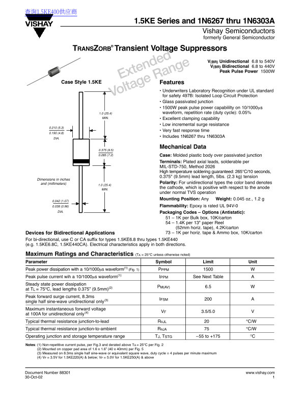
Page 1 Text Content
查询1.5KE400供应商
1.5KE Series and 1N6267 thru 1N6303A
Vishay Semiconductors formerly General Semiconductor
TRANSZORB® Transient Voltage Suppressors
V(BR) Unidirectional 6.8 to 540V V(BR) Bidirectional 6.8 to 440V Peak Pulse Power 1500W
Extended
Case Style 1.5KE Features
• Underwriters Laboratory Recognition under UL standard
Voltage Range for safety 497B: Isolated Loop Circuit Protection
• Glass passivated junction • 1500W peak pulse power capabililty on 10/1000µs 1.0 (25.4) waveform, repetition rate (duty cycle): 0.05%
MIN. • Excellent clamping capability
• Low incremental surge resistance
• Very fast response time
• Includes 1N6267 thru 1N6303A
Mechanical Data
0.375 (9.5) 0.285 (7.2) Case: Molded plastic body over passivated junction
Terminals: Plated axial leads, solderable per MIL-STD-750, Method 2026 High temperature soldering guaranteed: 265°C/10 seconds, 0.375" (9.5mm) lead length, 5lbs. (2.3 kg) tension
Dimensions in inches
and (millimeters) Polarity: For unidirectional types the color band denotes
the cathode, which is positive with respect to the anode
under normal TVS operation Mounting Position: Any Weight: 0.045 oz., 1.2 g
0.038 (0.96) Flammability: Epoxy is rated UL 94V-0
DIA. Packaging Codes – Options (Antistatic):
51 – 1K per Bulk box, 10K/carton 54 – 1.4K per 13" paper Reel (52mm horiz. tape), 4.2K/carton Devices for Bidirectional Applications 73 – 1K per horiz. tape & Ammo box, 10K/carton
For bi-directional, use C or CA suffix for types 1.5KE6.8 thru types 1.5KE440 (e.g. 1.5KE6.8C, 1.5KE440CA). Electrical characteristics apply in both directions.
Maximum Ratings and Characteristics (TA = 25°C unless otherwise noted) Parameter Symbol Limit Unit Peak power dissipation with a 10/1000µs waveform(1) (Fig. 1) PPPM Peak pulse current wih a 10/1000µs waveform(1) IPPM See Next Table Steady state power dissipation
PM(AV) 6.5 Wat TL
= 75OC, lead lengths 0.375” (9.5mm)(2) Peak forward surge current, 8.3ms
IFSM Asingle half sine-wave unidirectional only(3)
Maximum instantaneous forward voltage
VF 3.5/5.0 Vat 100A
for unidirectional only(4) Typical thermal resistance junction-to-lead RθJL °C/W Typical thermal resistance junction-to-ambient RθJA °C/W Operating junction and storage temperature range TJ, TSTG –55 to +175 OC Notes: (1) Non-repetitive current pulse, per Fig.3 and derated above TA = 25°C per Fig. 2 (2) Mounted on copper pad area of 1.6 x 1.6” (40 x 40mm) per Fig. 5 (3) Measured on 8.3ms single half sine-wave or equivalent square wave, duty cycle = 4 pulses per minute maximum (4) VF = 3.5V for 1.5KE220(A) & below; VF = 5.0V for 1.5KE250(A) & above
Document Number 88301 www.vishay.com 30-Oct-02
Page Summary Contents For Vishay Semiconductors 1.5KE Series and 1N6267 thru 1N6303A Owner's Manual and User Guide
Manual Details
| Brand | Vishay |
|---|---|
| Pages | 6 |
| File Size | 109.29 KB |
| Published | May 30, 2026 |
Enter the captcha to get the download link:

Frequently Asked Questions
What is the peak pulse power capacity of the 1.5KE series?
It has a peak pulse power capability of 1500 W on a 10/1000µs waveform.
Are there special types for bidirectional applications?
Yes, use a 'C' or 'CA' suffix (e.g., 1.5KE6.8C) for bi-directional use, and the electrical characteristics apply in both directions.
What is the recommended soldering temperature and lead length?
High temperature soldering is guaranteed at 265°C for 10 seconds with a 0.375" (9.5mm) lead length.
What are the typical thermal resistance values?
The typical junction-to-lead ($\theta_{JL}$) resistance is $20 °C/W$, while the junction-to-ambient ($\theta_{JA}$) resistance is $75 °C/W$.