Vishay TSOP11 Manual and User Guide
Summary
The TSOP11xx series offers miniaturized, high-performance infrared (IR) receiver modules designed for advanced remote control systems. This manual provides comprehensive engineering details, including electrical specifications, detailed application circuits, and performance graphs on sensitivity in varying ambient light conditions. Ideal for electronics designers and engineers developing products requiring reliable short-burst transmission decoding capability and compatibility with microprocessors.
Page 1 Text Content
TSOP11..
VISHAY
Vishay Semiconductors
IR Receiver Modules for Remote Control Systems
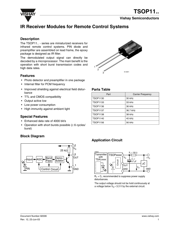
Description The TSOP11.. - series are miniaturized receivers for infrared remote control systems. PIN diode and preamplifier are assembled on lead frame, the epoxy package is designed as IR filter. The demodulated output signal can directly be decoded by a microprocessor. The main benefit is the operation with short burst transmission codes and high data rates.
Features Photo detector and preamplifier in one package Internal filter for PCM frequency Improved shielding against electrical field distur- Parts Table bance
Part Carrier Frequency
TTL and CMOS compatibility
TSOP1130 30 k Hz
Output active low
TSOP1133 33 k Hz
Low power consumption
TSOP1136 36 k Hz
High immunity against ambient light
TSOP1137 36.7 k Hz TSOP1138 38 k Hz
Special Features
ir cu it
TSOP1140 40 k Hz
Enhanced data rate of 4000 bit/s
TSOP1156 56 k Hz
Operation with short bursts possible (≥ 6 cycles/ burst)
Block Diagram
Application Circuit
Transmitter TSOPxxxx with VS +VS
Band OUTDemo-
TSALxxxx
Pass AGCInput dulator 4.7 µF
PIN Control GND GND GND
Circuit
R1 C1 recommended to suppress power supply disturbances. The output voltage should not be hold continuously at voltage below VO 3.3 by the external circuit.
Document Number 82006 www.vishay.com Rev. 12, 23-Jun-03
Page Summary Contents For Vishay TSOP11 Manual and User Guide
Manual Details
| Brand | Vishay |
|---|---|
| Pages | 7 |
| File Size | 231.45 KB |
| Published | May 30, 2026 |
Enter the captcha to get the download link:

Frequently Asked Questions
What is the recommended external circuit setup for optimal performance?
It is recommended to use a resistor and capacitor on the circuit to suppress power supply disturbances.
Which models support an enhanced data rate and short bursts?
The TSOP1140 offers an enhanced data rate of 4000 bit/s and supports operation with short bursts.
Are these infrared receivers compatible with different digital logic levels?
Yes, the modules offer compatibility with both TTL and CMOS circuits.
What is the functional operating temperature range for the module?
The specified ambient operating temperature range (T amb) is from -25 to +85 °C.