Vishay BYV28 ... User Guide and Manual
Summary
These high-performance Ultra Fast Avalanche Diodes are designed for demanding power electronics applications requiring rapid switching, such as switch mode power supplies. This technical manual provides comprehensive specifications, including detailed electrical characteristics, thermal resistance curves, and mechanical data for the SOD-64 package. Ideal for engineers and designers fabricating robust, highly efficient circuits that require controlled avalanche behavior and microsecond-level rectification performance.
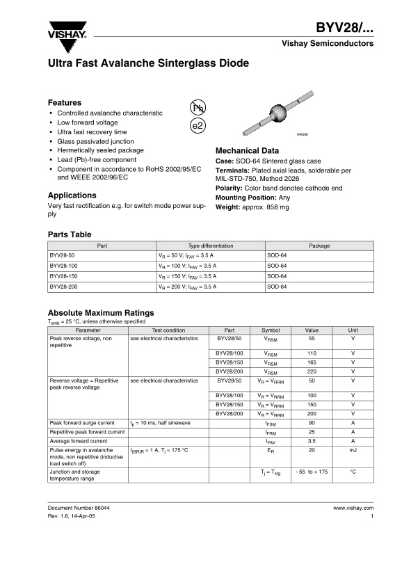
Page 1 Text Content
BYV28/... Vishay Semiconductors
Ultra Fast Avalanche Sinterglass Diode
Features Controlled avalanche characteristic Low forward voltage
Ultra fast recovery time Glass passivated junction Hermetically sealed package Mechanical Data Lead (Pb)-free component Case: SOD-64 Sintered glass case Component in accordance to Ro HS 2002/95/EC Terminals: Plated axial leads, solderable per and WEEE 2002/96/EC MIL-STD-750, Method 2026
Polarity: Color band denotes cathode end
Applications
Mounting Position: Any
Very fast rectification e.g. for switch mode power sup- Weight: approx. 858 mg ply
Parts Table
Part Type differentiation Package
BYV28-50 VR = 50 V; IFAV = 3.5 A SOD-64
BYV28-100 VR = 100 V; IFAV = 3.5 A SOD-64
BYV28-150 VR = 150 V; IFAV = 3.5 A SOD-64
BYV28-200 VR = 200 V; IFAV = 3.5 A SOD-64
Absolute Maximum Ratings Tamb = 25 °C, unless otherwise specified
Parameter Test condition Part Symbol Value Unit
Peak reverse voltage, non see electrical characteristics BYV28/50 VRSM repetitive
BYV28/100 VRSM BYV28/150 VRSM BYV28/200 VRSM
Reverse voltage = Repetitive see electrical characteristics BYV28/50 VR = VRRM peak reverse voltage
BYV28/100 VR = VRRM BYV28/150 VR = VRRM BYV28/200 VR = VRRM
Peak forward surge current tp = 10 ms, half sinewave IFSM Repetitive peak forward current IFRM Average forward current IFAV 3.5
Pulse energy in avalanche I(BR)R = 1 A, Tj = 175 °C ER m J
mode, non repetitive (inductive load switch off) Junction and storage Tj = Tstg - 55 to + 175 °C temperature range
Document Number 86044 www.vishay.com Rev. 1.6, 14-Apr-05
Page Summary Contents For Vishay BYV28 ... User Guide and Manual
Manual Details
| Brand | Vishay |
|---|---|
| Pages | 5 |
| File Size | 114.35 KB |
| Published | June 15, 2026 |
Enter the captcha to get the download link:

Frequently Asked Questions
What is the maximum average forward current (I_F(AV)) rating for this diode?
The maximum average forward current (I_F(AV)) is 3.5 A.
How does ambient temperature affect performance?
The datasheet provides charts showing parameters like max average forward current change with varying ambient temperatures up to 175 °C.
Does this component comply with modern environmental regulations?
Yes, it is a Lead (Pb)-free component and adheres to RoHS 2002/95/EC and WEEE 2002/96/EC standards.
What polarity indicators are used during assembly?
The color band denotes the cathode end, making polarization easier when installing the component.