Vishay EB4 User Guide and Manual
Summary
These highly versatile Vishay Dale EB4 Edgeboard Connectors offer reliable, high-performance electrical interconnection solutions for complex PCB designs. The manual provides exhaustive details on multiple body materials, standard/right angle terminals, and customizable grid patterns. Designed for engineers requiring precision connectivity across a wide temperature range (–65°C to +125°C), this comprehensive guide helps users specify connectors with optimal design latitude and robust electrical integrity for demanding industrial or military applications.
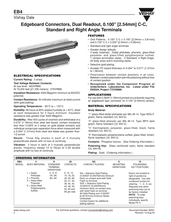
Page 1 Text Content
EB4 Vishay Dale Edgeboard Connectors, Dual Readout, 0.100" [2.54mm] C-C,
Standard and Right Angle Terminals
FEATURES Grid Patterns: 0.100" C-C x 0.150" [2.54mm x 3.81mm] and 0.100" C-C x 0.200" [2.54mm x 5.08mm]. Standard and right angle terminals. Greater design latitude: 4 body materials: Diallyl phthalate, phenolic, glass-filled polyester and glass-filled polyphenylene sulfied. 7 contact termination styles - 3 Standard, 4 Right Angle. 20 body sizes and 6 mounting styles. Selective gold plating. Accepts PC board thickness of 0.054" to 0.071" [1.37mm to 1.80mm]. Polarization between contact positions in all sizes.
ELECTRICAL SPECIFICATIONS
Between contact polarization permits polarizing without loss
Current Rating: 3 amps.
of contact position.
Test Voltage Between Contacts:
Recognized under the Component Program of
At sea level: 650VRMS. Underwriters Laboratories, Inc. Listed under File At 70,000 feet [21,336 meters]: 275VRMS. E65524, Project 77CH3889. Insulation Resistance: 5000 Megohm minimum at 500VDC
APPLICATIONS
potential.
For use with 0.0625" [1.59mm] printed circuit boards requiring
Contact Resistance: 30 millivolts maximum at rated current
an edgeboard type connector on 0.100" [2.54mm] centers.
(with gold plating).
Operating Temperature: - 65°C to + 125°C. MATERIAL SPECIFICATIONS
Humidity: 96 hours at 90% relative humidity at + 40°C, dried Body Material: at room temperature for 3 hours minimum, insulation
“1” glass-filled diallyl phthalate per MIL-M-14, Type SDG-F
resistance was greater than 5000 Megohm.
green, flame retardant (UL 94V-0).
Durability: After 500 cycles of insertion and withdrawal of a
“2” glass-filled phenolic per MIL-M-14, Type MFH dark
0.070" [1.78mm] thick steel test board, contact resistance
green, flame retardant (UL 94V-0).
less than 0.030V at 3 amps on gold plated contacts and
individual contact pair separation force when measured with “3” thermoplastic polyester, glass-filled, black, flame a 0.054" [1.37mm] thick steel test blade was greater than retardant (UL 94V-0).
1/2 ounce. “5” thermoplastic polyphenylene sulfied, glass filled, brown,
Shock: Three 50g shocks in each of 3 mutually flame retardant (UL 94V-0).
perpendicular planes with no loss of continuity.
Contacts: Phosphor bronze. (See Ordering Information.)
Vibration: 2 hours in each of 3 mutually perpendicular
Polarizing Key: Glass reinforced nylon, flame retardant
planes, frequency sweep 10 to 55cps at 0.06 double
(UL 94H-B).
amplitude with no loss of continuity.
Plating: Gold. (Ordering Information.)
ORDERING INFORMATION
EB4 SG
MODEL BODY MATERIAL STANDARD CONTACTS CONTACT PLATING MOUNTING POLARIZING
TERMINAL VARIATIONS KEY POSITIONS VARIATIONS Diallyl C, D, K, 6, 10, 12, SG = Selective Gold Plating Key(s) are located to
Phthalate 1R, 2R, 15, 18, 20, (0.00003" [0.000762mm] minimum right of position(s) Phenolic 3R, 4R 22, 25, 28, thick) on contact area with Gold designated. Use odd- Glass-filled 30, 31, 35, Flash on terminal.
numbered contact for
Polyester 36, 40, 43, SGF = Selective Gold Plating
ordering: -1, -3, -5, etc.
Glass-filled (0.000010" [0.000254mm]
44, 48, 49, Required only when
Polyphenylene minimum thick) on contact area
50, 60 and polarizing keys are to
Sulfied with Gold Flash on terminal.
65 per side. be factory installed.
All Gold Plating over 0.00005"
NOTE: To order
[0.00127mm] minimum Nickel
polarizing keys
Underplate.
individually, specify
Contact factory for additional
Model PK-4.
plating options.
www.vishay.com For technical questions, contact [email protected] Document Number 36001
Revision 14-Aug-02
Page Summary Contents For Vishay EB4 User Guide and Manual
Manual Details
| Brand | Vishay |
|---|---|
| Pages | 4 |
| File Size | 158.89 KB |
| Published | June 16, 2026 |
Enter the captcha to get the download link:

Frequently Asked Questions
What is the maximum current rating for this connector?
The rated current is 3 amps for a single contact position.
Does this connector support different PCB thicknesses?
It accepts PC board thickness ranging from 0.054" to 0.071" [1.37mm to 1.80mm].
What are the specified operating conditions (temperature/humidity)?
The operating temperature range is -65°C to +125°C, and it withstands humidity for 96 hours at 90% relative humidity at +40°C.
Is the connector durable enough for shocks or vibrations?
It can endure three 50g shocks in each of three perpendicular planes with no loss of continuity, as well as vibration in all three axes.