Vishay TSOP11..RF1 Specifications User Guide
Summary
These miniaturized infrared photo receivers are essential components for interfacing with remote control systems. Designed for embedded electronics designers, this series decodes varied IR frequencies across multiple channels (30 kHz to 56 kHz), making reliable signal reception possible for microprocessors. The comprehensive manual details advanced features such as high data rates, support for complex encoding protocols (e.g., RECS-80), and superior immunity against ambient light and electrical noise, ensuring stable system integration in demanding applications.
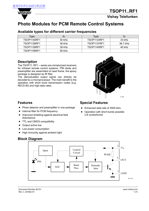
Page 1 Text Content
查询TSOP1136RF1供应商
TSOP11..RF1 Vishay Telefunken
Photo Modules for PCM Remote Control Systems Available types for different carrier frequencies Type fo Type fo TSOP1130RF1 30 k Hz TSOP1133RF1 33 k Hz TSOP1136RF1 36 k Hz TSOP1137RF1 36.7 k Hz TSOP1138RF1 38 k Hz TSOP1140RF1 40 k Hz TSOP1156RF1 56 k Hz
Description The TSOP11..RF1 – series are miniaturized receivers for infrared remote control systems. PIN diode and preamplifier are assembled on lead frame, the epoxy package is designed as IR filter. The demodulated output signal can directly be decoded by a microprocessor. The main benefit is the operation with short burst transmission codes (e.g. RECS 80) and high data rates.
Features Special Features Photo detector and preamplifier in one package Enhanced data rate of 3500 bit/s Internal filter for PCM frequency
Operation with short bursts possible Improved shielding against electrical field (≥6 cycles/burst)
disturbance TTL and CMOS compatibility Output active low Low power consumption High immunity against ambient light
Block Diagram
Control
Input
Circuit
Band Demodu-
Pass lator
GND 94 8136
www.vishay.com Document Number 82151
1 (7)Rev. 3, 29-Mar-01
Page Summary Contents For Vishay TSOP11..RF1 Specifications User Guide
Manual Details
| Brand | Vishay |
|---|---|
| Pages | 8 |
| File Size | 157.23 KB |
| Published | June 03, 2026 |
Enter the captcha to get the download link:

Frequently Asked Questions
What types of infrared signal codes are supported by this receiver?
It supports various data formats including NEC Code, Toshiba Micom Format, Sharp Code, and RC5 disturbance signals.
What is the suitable voltage range for powering the device (Pin 2)?
The supply voltage (Pin 2) ranges from -0.3V to 6.0V.
How robust is the receiver against electrical interference?
It features an internal filter and automatic gain control (AGC) stage, improving immunity against noise and ambient light.
What warnings must be followed regarding product usage?
Users must validate all operating parameters for their specific application and shall indemnify against unauthorized use.