Vishay VLME31... User's Manual
Summary
Harness the exceptional brightness of these high-intensity SMD LEDs, designed for demanding applications across automotive, telecommunications, and industrial electronics. The VLME31 series offers robust, RoHS-compliant performance, making it perfect for backlighting dashboards, indicating switches, and powering general LCD systems. This technical guide provides comprehensive engineering data, covering electrical ratings, detailed optical characteristics (yellow spectrum), thermal limits, and compatibility with mainstream soldering processes like reflow and wave solder, helping engineers select the ideal component for their precise design needs.
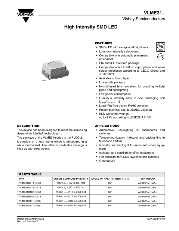
Page 1 Text Content
VLME31..
Vishay Semiconductors
High Intensity SMD LED
FEATURES SMD LED with exceptional brightness Luminous intensity categorized Compatible with automatic placement
equipment EIA and ICE standard package Compatible with IR Reflow, vapor phase and wave solder processes according to CECC 00802 and J-STD-020C Available in 8 mm tape Low profile package Non-diffused lens: excellent for coupling to light pipes and backlighting Low power consumption Luminous intensity ratio in one packaging unit IVmax/IVmin ≤ 1.6 Lead (Pb)-free device-Ro HS compliant Preconditioning: acc. to JEDEC Level 2a ESD-withstand voltage: up to 2 k V according to JESD22-A114-B
DESCRIPTION APPLICATIONS This device has been designed to meet the increasing Automotive: Backlighting in dashboards and demand for Al In Ga P technology. switches The package of the VLME31-series is the PLCC-2. Telecommunication: Indicator and backlighting in It consists of a lead frame which is embedded in a telephone and fax white thermoplast. The reflector inside this package is Indicator and backlight for audio and video equip- filled up with clear epoxy. ment Indicator and backlight in office equipment Flat backlight for LCDs, switches and symbols General use
PARTS TABLE PART COLOR, LUMINOUS INTENSITY ANGLE OF HALF INTENSITY (± ϕ) TECHNOLOGY
VLME31Q2T1-GS08 Yellow, IV = (90 to 355) mcd 60° Alln Ga P on Ga As
VLME31Q2T1-GS18 Yellow, IV = (90 to 355) mcd 60° Alln Ga P on Ga As
VLME31R1S2-GS08 Yellow, IV = (112 to 280) mcd 60° Alln Ga P on Ga As
VLME31R1S2-GS18 Yellow, IV = (112 to 280) mcd 60° Alln Ga P on Ga As
VLME31S1T1-GS08 Yellow, IV = (180 to 355) mcd 60° Alln Ga P on Ga As
VLME31S1T1-GS18 Yellow, IV = (180 to 355) mcd 60° Alln Ga P on Ga As
Document Number 81324 www.vishay.com Rev. 1.0, 09-May-06
Page Summary Contents For Vishay VLME31... User's Manual
Manual Details
| Brand | Vishay |
|---|---|
| Pages | 10 |
| File Size | 199.85 KB |
| Published | June 15, 2026 |
Enter the captcha to get the download link:

Frequently Asked Questions
Are the VLME31 LEDs compatible with different soldering processes?
Yes, they are compatible with IR Reflow, vapor phase, and wave solder processes according to CECC 00802 and J-STD-020C.
Is this a lead-free device and what compliance standards apply?
It is a Lead (Pb)-free device and is RoHS compliant.
What are the operational temperature limits for the device?
The operating temperature range is -40 to +100 °C ambient, with a storage range of -40 to +100 °C.
How does the luminous intensity vary with different parts?
Different part numbers offer specific luminous intensities in mcd, such as 90-355 mcd for VLME31Q2T1.