# A B C D E F G H I J K L M N O P Q R S T U V W X Y Z

Vishay TSOP362.. User Guide Manual

Summary

Miniaturized SMD IR Receiver modules designed for reliable remote control systems. The TSOP362 series offers high immunity against ambient light and is compatible with microprocessors, supporting multiple standard frequency bands (e.g., 30kHz–56kHz). This documentation provides detailed electrical characteristics, application circuits, mechanical data, and performance curves necessary for engineers designing stable embedded and remote communication solutions. Ensure optimal signal reception in varied environments.
📄 Preview 📖 Table of Contents Contents PAGE OF 15

Page 1 Text Content

TSOP362..

VISHAY

Vishay Semiconductors

IR Receiver Modules for Remote Control Systems

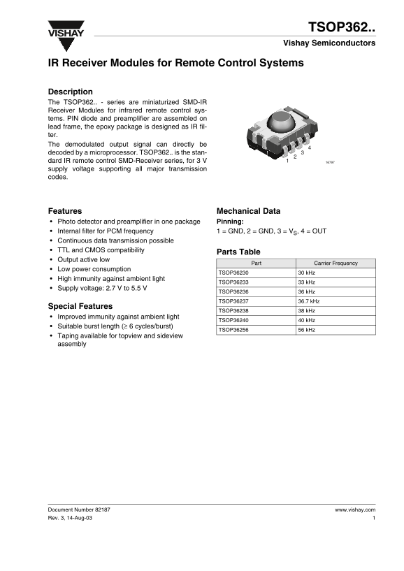
Description The TSOP362.. - series are miniaturized SMD-IR Receiver Modules for infrared remote control sys- tems. PIN diode and preamplifier are assembled on lead frame, the epoxy package is designed as IR fil- ter. The demodulated output signal can directly be decoded by a microprocessor. TSOP362.. is the stan- dard IR remote control SMD-Receiver series, for 3 V supply voltage supporting all major transmission codes.

Features Mechanical Data Photo detector and preamplifier in one package Pinning: Internal filter for PCM frequency 1 = GND, 2 = GND, 3 = VS, 4 = OUT Continuous data transmission possible TTL and CMOS compatibility

Parts Table

Output active low

Part Carrier Frequency

Low power consumption

TSOP36230 30 k Hz

High immunity against ambient light

TSOP36233 33 k Hz

Supply voltage: 2.7 V to 5.5 V

TSOP36236 36 k Hz

TSOP36237 36.7 k Hz

Special Features

TSOP36238 38 k Hz

Improved immunity against ambient light

TSOP36240 40 k Hz

Suitable burst length (≥ 6 cycles/burst)

TSOP36256 56 k Hz

Taping available for topview and sideview assembly

Document Number 82187 www.vishay.com Rev. 3, 14-Aug-03

Page Summary Contents For Vishay TSOP362.. User Guide Manual

Page 1 TSOP362.. VISHAY Vishay Semiconductors IR Receiver Modules for Remote Control Systems Description The TSOP362.. - series are miniaturized SMD-IR Receiver Modules for infrared remote control sys- tems....
Page 2 VISHAYTSOP362.. Vishay Semiconductors Block Diagram Application Circuit Transmitter HSxxxx OUTDemo- with VS +VS AGCInput C1 TSALxxxx Pass dulator PIN Control Circuit GND GND GND R1 C1 recommended to s...
Page 3 TSOP362.. VISHAY Vishay Semiconductors ut pu t P ul se id th po Parameter Test condition Symbol Min Typ. Max Unit Irradiance (30-40 k Hz) VS = 5 V Ee min 0.45 0.6 Pulse width tolerance: tpi - 5/fo &lt...
Page 4 VISHAYTSOP362.. hr es ho ld Ir ra di an ce /m hr es ho ld Ir ra di an ce /m / E el . R es po ns iv ity in in in Vishay Semiconductors f/f0 – Relative Frequency16925 94 8147 E – Field Strength of Distu...
Page 5 TSOP362.. VISHAY Vishay Semiconductors en si tiv ity /m el at iv pe ct ra l S en si tiv ity in re – Wavelength ( nm )16919 Figure 11. Relative Spectral Sensitivity vs. Wavelength drel Relative Transmi...
Page 6 VISHAYTSOP362.. Vishay Semiconductors Suitable Data Format The circuit of the TSOP362.. is designed in that way that unexpected output pulses due to noise or distur- bance signals are avoided. A bandp...
Page 7 TSOP362.. VISHAY Vishay Semiconductors Package Dimensions in mm Assembly Instructions • Recommended soldering paste (composition: SN 63 %, Pb 37 %) Melting temperature 178 °C to 192 °C Reflow Solderin...
Page 8 VISHAYTSOP362.. Vishay Semiconductors • Recommended thickness of metal mask is 0.2 mm Reflow Solder Profile for screen printing. • The recommended reflow furnace is a combination- type with upper and ...
Page 9 TSOP362.. VISHAY Vishay Semiconductors Taping Version TSOP..TT Document Number 82187 www.vishay.com Rev. 3, 14-Aug-03
Page 10 VISHAYTSOP362.. Vishay Semiconductors Taping Version TSOP..TR www.vishay.com Document Number 82187 Rev. 3, 14-Aug-03
Page 11 TSOP362.. VISHAY Vishay Semiconductors Reel Dimensions Document Number 82187 www.vishay.com Rev. 3, 14-Aug-03
Page 12 VISHAYTSOP362.. Vishay Semiconductors Leader and Trailer Trailer Leader no devices devices no devices Start End min. min. Cover Tape Peel Strength According to DIN EN 60286-3 0.1 to 1.3 N 300 ± 10 mm/...
Page 13 TSOP362.. VISHAY Vishay Semiconductors Vishay Semiconductor Gmb H standard bar code product label (finished goods) Plain Writing Abbreviation Length Item-Description Item-Number INO Selection-Code SEL...
Page 14 VISHAYTSOP362.. Vishay Semiconductors Recommended Method of Storage Dry box storage is recommended as soon as the alu- minium bag has been opened to prevent moisture absorption. The following conditio...
Page 15 TSOP362.. VISHAY Vishay Semiconductors Ozone Depleting Substances Policy Statement It is the policy of Vishay Semiconductor Gmb H to 1. Meet all present and future national and international statutory...

Manual Details

Brand Vishay
Pages 15
File Size 728.71 KB
Published June 03, 2026
41 views

Enter the captcha to get the download link:

captcha

Frequently Asked Questions

What is the required supply voltage range for power?

The TSOP362.. supports a wide supply voltage range of 2.7 V to 5.5 V.

How can I connect the output signal for decoding?

Pin 4 (OUT) provides the demodulated output signal that can be directly decoded by a microprocessor.

Is there a specific recommended circuit setup?

A resistor (R) and capacitor (C) are recommended to suppress power supply disturbances, and the output should not be held continuously below 2.0 V.

What is the maximum measurable transmission distance?

The maximum listed transmission distance for testing environments is up to 35 meters.