Vishay Thin Film SOT-23 Specifications and User Guide
Summary
Enhance your circuit designs with MPM Vishay Thin Film Resistor Dividers. These surface-mount network resistors offer exceptional stability and ultra-tight ratio tolerances down to 0.01%, making them ideal for precise measuring and dividing tasks. Available in compact SOT-23 packages, they ensure reliable performance across various temperature ranges. This manual provides comprehensive specifications, application guidelines, part numbering systems, and electrical details for engineers requiring high-precision component solutions for demanding electronic applications.
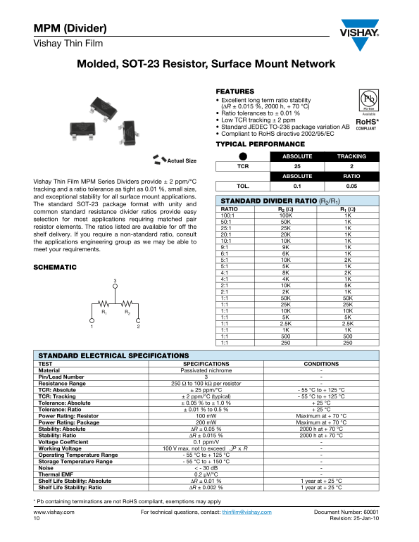
Page 1 Text Content
MPM (Divider) Vishay Thin Film
Molded, SOT-23 Resistor, Surface Mount Network
FEATURES Excellent long term ratio stability (ΔR ± 0.015 %, 2000 h, + 70 °C) Ratio tolerances to ± 0.01 % Low TCR tracking ± 2 ppm Standard JEDEC TO-236 package variation AB Compliant to Ro HS directive 2002/95/EC TYPICAL PERFORMANCE
ABSOLUTE TRACKING
Actual Size
ABSOLUTE RATIO
Vishay Thin Film MPM Series Dividers provide ± 2 ppm/°C
TOL. 0.1 0.05
tracking and a ratio tolerance as tight as 0.01 %, small size, and exceptional stability for all surface mount applications.
STANDARD DIVIDER RATIO (R2/R1)
The standard SOT-23 package format with unity and
RATIO R2 (Ω) R1 (Ω)
common standard resistance divider ratios provide easy
selection for most applications requiring matched pair
resistor elements. The ratios listed are available for off the 25:1 25K 1K shelf delivery. If you require a non-standard ratio, consult 20:1 20K 1K
the applications engineering group as we may be able to 10:1 10K 1K 9:1 9K 1K
meet your requirements.
6:1 6K 1K 5:1 10K 2K SCHEMATIC 5:1 5K 1K 4:1 8K 2K 4:1 4K 1K 2:1 10K 5K 2:1 2K 1K 1:1 50K 50K 1:1 25K 25K R1 R2 1:1 10K 10K 1:1 5K 5K 1:1 2.5K 2.5K 1:1 1K 1K 1:1 1:1
STANDARD ELECTRICAL SPECIFICATIONS TEST SPECIFICATIONS CONDITIONS Material Passivated nichrome Pin/Lead Number Resistance Range 250 Ω to 100 kΩ per resistor TCR: Absolute ± 25 ppm/°C - 55 °C to + 125 °C TCR: Tracking ± 2 ppm/°C (typical) - 55 °C to + 125 °C Tolerance: Absolute ± 0.05 % to ± 1.0 % + 25 °C Tolerance: Ratio ± 0.01 % to 0.5 % + 25 °C Power Rating: Resistor 100 m W Maximum at + 70 °C Power Rating: Package 200 m W Maximum at + 70 °C Stability: Absolute ΔR ± 0.05 % 2000 h at + 70 °C Stability: Ratio ΔR ± 0.015 % 2000 h at + 70 °C Voltage Coefficient 0.1 ppm/V
Working Voltage 100 V max. not to exceed - P x R
Operating Temperature Range - 55 °C to + 125 °C Storage Temperature Range - 55 °C to + 150 °C Noise < - 30 d B Thermal EMF 0.2 μV/°C Shelf Life Stability: Absolute ΔR ± 0.01 % 1 year at + 25 °C Shelf Life Stability: Ratio ΔR ± 0.002 % 1 year at + 25 °C
* Pb containing terminations are not Ro HS compliant, exemptions may apply
www.vishay.com For technical questions, contact: [email protected] Document Number: 60001 Revision: 25-Jan-10
Page Summary Contents For Vishay Thin Film SOT-23 Specifications and User Guide
Manual Details
| Brand | Vishay |
|---|---|
| Pages | 3 |
| File Size | 285.01 KB |
| Published | May 28, 2026 |
Enter the captcha to get the download link:

Frequently Asked Questions
What is the specified operating temperature range for these resistors?
The components are rated for an Operating Temperature Range of -55 °C to +125 °C
How can I order a resin ratio that isn't standard?
You must consult the applications engineering group as they may be able to meet your specific requirements
What determines the maximum recommended working voltage?
The working voltage should not exceed P x R
Are these resistive dividers compatible with RoHS standards?
Yes, this resilient divider is Compliant to RoHS directive 2002/95/EC