Vishay CNY17F Specifications and User Guide
Summary
The CNY17F series is a reliable optocoupler that transmits signals between two electrically isolated circuits. Featuring a gallium arsenide infrared emitter coupled to a silicon phototransistor, this component ensures signal integrity while providing robust galvanic isolation barrier. The accompanying manual provides comprehensive technical specifications—including detailed electrical characteristics (Current Transfer Ratio, leakage current) and absolute maximum ratings—to guide engineers in selecting the proper configurable variant (e.g., DIP-6 or SMD packages). Ideal for electronics designers requiring reliable, long-term signal coupling with enhanced common-mode interference immunity.
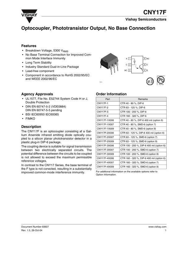
Page 1 Text Content
CNY17F Vishay Semiconductors
Optocoupler, Phototransistor Output, No Base Connection
Features Breakdown Voltage, 5300 VRMS No Base Terminal Connection for Improved Com- mon Mode Interface Immunity NC Long Term Stability Industry Standard Dual-in-Line Package
Lead-free component Component in accordance to Ro HS 2002/95/EC and WEEE 2002/96/EC
e3 Pb Pb-free
Agency Approvals Order Information UL1577, File No. E52744 System Code H or J, Part Remarks Double Protection
CNY17F-1 CTR 40 - 80 %, DIP-6
DIN EN 60747-5-2 (VDE0884)
CNY17F-2 CTR 63 - 125 %, DIP-6
DIN EN 60747-5-5 pending
CNY17F-3 CTR 100 - 200 %, DIP-6
BSI IEC60950 IEC60065
CNY17F-4 CTR 160 - 320 %, DIP-6
FIMKO
CNY17F-1X006 CTR 40 - 80 %, DIP-6 400 mil (option 6)
CNY17F-1X007 CTR 40 - 80 %, SMD-6 (option 7)
Description
CNY17F-1X009 CTR 40 - 80 %, SMD-6 (option 9)
The CNY17F is an optocoupler consisting af a Gal-
CNY17F-2X006 CTR 63 - 125 %, DIP-6 400 mil (option 6)
lium Arsenide infrared emitting diode optically cou-
CNY17F-2X007 CTR 63 - 125 %, SMD-6 (option 7)
pled to a silicon planar phototransistor detector in a
CNY17F-2X009 CTR 63 - 125 %, SMD-6 (option 9)
plastic plug-in DIP-6 package.
CNY17F-3X006 CTR 100 - 200 %, DIP-6 400 mil (option 6)
The coupling device is suitable for signal transmission
between two electrically separated circuits. The CNY17F-3X007 CTR 100 - 200 %, SMD-6 (option 7)
potential difference between the circuits to be coupled CNY17F-3X009 CTR 100 - 200 %, SMD-6 (option 9) is not allowed to exceed the maximum permissible
CNY17F-4X006 CTR 160 - 320 %, DIP-6 400 mil (option 6)
reference voltages.
CNY17F-4X007 CTR 160 - 320 %, SMD-6 (option 7)
In contrast to the CNY17 Series, the base terminal of
CNY17F-4X009 CTR 160 - 320 %, SMD-6 (option 9)
the F type is not conected, resulting in a substantially
For additional information on the available options refer to
improved common-mode interference immunity.
Option Information.
Document Number 83607 www.vishay.com Rev. 1.5, 26-Oct-04
Page Summary Contents For Vishay CNY17F Specifications and User Guide
Manual Details
| Brand | Vishay |
|---|---|
| Pages | 10 |
| File Size | 1.91 MB |
| Published | June 05, 2026 |
Enter the captcha to get the download link:

Frequently Asked Questions
What can the CNY17F optocoupler be used for?
It is designed for signal transmission between two electrically separated circuits.
Are these components suitable for medical or life-support applications?
No, the products are not designed for use in medical, life-saving, or life-sustaining applications.
What is the maximum isolation test voltage rating?
The device features a high isolation test voltage of 5300 V RMS.