Vishay TFDU4300 Specifications and User Guide
Summary
This low-profile infrared transceiver module provides robust IrDA data communication up to 115.2 kbit/s, using an integrated front-end solution perfect for battery-powered devices. The manual comprehensively details its specifications, including tri-state output capabilities, variable logic voltage compatibility (1.5V–5.5V), and extended low power range operation. It is designed for professionals developing portable electronics such as notebook computers, PDAs, cellular phones, industrial data loggers, and consumer digital cameras requiring high reliability.
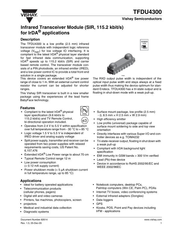
Page 1 Text Content
TFDU4300 Vishay Semiconductors
Infrared Transceiver Module (SIR, 115.2 kbit/s) for Ir DA® applications Description The TFDU4300 is a low profile (2.5 mm) infrared transceiver module with independent logic reference voltage (Vlogic) for low voltage IO interfacing. It is compliant to the latest Ir DA® physical layer standard for fast infrared data communication, supporting Ir DA® speeds up to 115.2 kbit/s (SIR) and carrier based remote control. The transceiver module con- sists of a PIN photodiode, an infrared emitter (IRED), and a low-power control IC to provide a total front-end solution in a single package. This device covers an extended Ir DA® low power The RXD output pulse width is independent of the
range of close to 1 m. With an external current control optical input pulse width and stays always at a fixed resistor the current can be adjusted for shorter pulse width thus making the device optimum for stan- ranges. dard Endecs. TFDU4300 has a tri-state output and is This Vishay SIR transceiver is built in a new smaller floating in shut-down mode with a weak pull-up.
package using the experiences of the lead frame Baby Face technology.
Features
Compliant to the latest Ir DA® physical Surface mount package, low profile (2.5 mm) layer specification (9.6 kbit/s to - (L 8.5 mm × H 2.5 mm × W 2.9 mm)
115.2 kbit/s) and TV Remote Control, High efficiency emitter
bi-directional operation included.
Low profile (universal) package capable of
Operates from 2.4 V to 5.5 V within specification surface mount soldering to side and top view over full temperature range from - 30 °C to + 85 °C orientation Logic voltage 1.5 V to 5.5 V is independent of Directly interfaces with various Super I/O and con- IRED driver and analog supply voltage troller devices as e.g. TOIM4232 Split power supply, transmitter and receiver can be Tri-state-receiver output, floating in shut down with operated from two power supplies with relaxed a weak pull-up requirements saving costs, US Patent No.
Compliant with Ir DA background light
specification
Extended Ir DA® Low Power range to about 70 cm
EMI immunity in GSM bands > 300 V/m verified
Typical Remote Control range 12 m
Lead (Pb)-free device
Low power consumption
Device in accordance to Ro HS 2002/95/EC and
(< 0.12 m A supply current)
WEEE 2002/96EC
Power shutdown mode (< 5 µA shutdown current in full temperature range, up to 85 °C)
Applications
• Ideal for battery operated applications • Notebook computers, desktop PCs, • Telecommunication products Palmtop computers (Win CE, Palm PC), PDAs (cellular phones, pagers) • Internet TV boxes, video conferencing systems • Digital still and video cameras • External infrared adapters (Dongles) • Printers, fax machines, photocopiers, screen • Data loggers • projectors • GPS • Medical and industrial data collection • Kiosks, POS, Point and Pay devices including • Diagnostic systems Ir FM - applications
Document Number 82614 www.vishay.com Rev. 1.5, 05-Dec-05
Page Summary Contents For Vishay TFDU4300 Specifications and User Guide
Manual Details
| Brand | Vishay |
|---|---|
| Pages | 18 |
| File Size | 276.49 KB |
| Published | June 15, 2026 |
Enter the captcha to get the download link:

Frequently Asked Questions
What is the supported data rate range for this transceiver?
The module supports IrDA speeds from 9.6 kbit/s up to 115.2 kbit/s.
Does the RXD output require external components (resistors)?
No, the RXD output is a push-pull driver with a weak pull-up in shutdown mode and does not need external resistors.
What are the operating voltage limits for the module?
The unit operates from 2.4 V to 5.5 V, and the independent logic reference voltage (V) must be between 1.5 V and 5.5 V.
How can I adjust the infrared emitter's current or pulse width?
You can adjust the IRED anode current by adding a resistor in series between the power supply and the IRED anode.